www.chamberlainanz.com MR1000 Rolling Garage Door Opener Installation and Operating Instructions Owners Copy: Please keep these instructions for future reference This manual contains IMPORTANT SAFETY information. DO NOT PROCEED WITH THE INSTALLATION BEFORE READING THOROUGHLY.
START BY READING THESE IMPORTANT SAFETY INSTRUCTIONS WARNING • Failure to comply with the following instructions may result in serious personal injury or property damage. • Read and follow all instructions carefully. • The garage door opener is designed and tested to offer safe service provided it is installed and operated in strict accordance with the instructions in this manual. These safety alert symbols mean WARNING : A possible risk to personal safety or property damage exists.
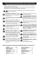
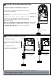
2 TOOLS REQUIRED 1 CARTON INVENTORY 1. Instruction manual (this document) 2. Stop collar 3. Drive forks 4. Release handle and cord 5. Transmitter (2) 6. Wireless wall control 7. Hardware bag 8. Weight bar 9. Warning label and risk of entrapment label 10.Lamp cover 1 2 4 5 1. Ladder 2. Adjustable wrench for U-bolts already installed on the door 3. 8mm socket, 10mm socket and 13mm extended socket and socket wrench 4. 12inch socket extension (for minimum side-room installations) 5. Drill and 5.
TESTING THE DOOR Disable all locks and remove any ropes connected to the garage door. Complete the following test to ensure your door is well balanced, and not sticking or binding: • Lift the door to about halfway and then release it. The door should remain spring balanced. NOTE: The spring should hold the door at any open position without creeping up or down. • Raise and lower the door to discover if there are any sticking or binding points.
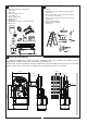
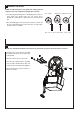
7 ATTACHING THE RELEASE HANDLE AND CORD • Thread one end of the rope through the hole in the top of the red handle so “NOTICE” reads right side up as shown. • Secure with an overhand knot at least 25mm from the end of the rope to prevent slipping. • Thread the other end of the rope through the loop of red clutch lever. • Adjust rope length so the handle is no higher than 1.8m above the floor. Secure with an overhand knot. If the door is greater than 2.
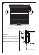
9 PINNING THE DOOR NOTE: A ballooning door may delay the safety reversal response and can compromise garage door security. • To remedy any ballooning, place self tapping metal screws or rivets where the curtain leaves the roll. Secure these through the curtain into the drum wheel at each end of the roll. Free curtain Ballooning Add fasteners here • After determining the correct fastener location as shown, lift the door approximately half a turn from the closed position to allow access for drilling.
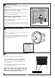
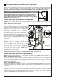
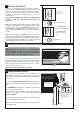
11 LEFT / RIGHT HAND INSTALLATION roller:L roller:L roller:L roller:L R R LEFT RIGHT Inside garage looking out Setting left / right operation fig 1 The opener must be set to either left or right hand operation via the dip switch located under the green activation button. roller:L roller:L R R open 180s 60s timer to close • Gently pry the flap down and away from the opener using a screw driver or pen.
12 INSTALLATION PROCEDURE Do not allow people to walk under or around the door during the installation process. Serious injury can occur. NOTE: The opener can be installed on either side of the door. The following instructions are for RIGHT HAND INSTALLATIONS (as illustrated i.e. inside the garage looking out). For left hand installations, reverse the instruction terminology (eg LEFT for RIGHT etc). Rope Door Stand Preparation: • Place the opener in manual release mode (refer section 8).
13 SETTING THE LIMITS FOR RIGHT OR LEFT OPERATION The travel limits regulate the points at which the door will stop when moving UP or DOWN. The procedure for setting these limits differs depending on which side of the garage door the opener has been fitted. eg As viewed from inside the garage looking out, is the opener on the right-hand or left-hand side. The opener must be fully installed on the door and all installation steps completed before proceeding. Make sure the door is clear of obstruction.
14 SETTING THE FORCE Setting the force The force, as measured on the closing edge of the door, should not exceed 400N (40kgf). If the closing force is measured to more than 400N, the Protector SystemTM must be installed (refer section 17). The force setting regulates the amount of power required to open and close the door. This procedure requires the door to be engaged (see section 8) and run through one full cycle of operation.
17 INSTALL THE PROTECTOR SYSTEM™ (IR BEAMS) SAFETY FIRST! Whilst Chamberlain have engineered safety features into your garage door opener, we urge you to consider fitting IR Beams to your new garage door opener. In many countries these devices are compulsory to prevent serious injury or property damage. For your own peace of mind and the safety of others please install this inexpensive safety device.
18 SETTING AUTO CLOSE (OPTIONAL) NOTE: The Protector SystemTM MUST be installed to enable this feature. The auto close feature will automatically close the garage door after the preset time. The time can be adjusted up to 180 seconds using the trim pot located on the control board. Auto close can be disabled by adjusting the trim pot to the 0s/off setting. Terminals Located under flap. Remove lamp cover: Auto close is NOT recommended for households with young children.
19 INSTALLING YOUR CM128 WIRELESS WALL BUTTON Disconnect power to the opener whilst installing this accessory to prevent accidental activation. Locate minimum 1.5m above the floor. To install: • Carefully pry open the CM128 and locate the two screws for mounting. • Attach to the wall using the two screws and wall anchors provided if mounting to a plaster wall. If using a recessed wall box do not use anchors. + + + NOTE: Do not overtighten screws.
21 KEYLESS DEVICE PROGRAMMING (OPTIONAL ACCESSORY) Programming C840 using the “learn” button: 1 Activate the opener only when door is in full view, free of obstruction and properly adjusted. No one should enter or leave garage while the door is in motion. Do not allow children to operate push button(s) or transmitter(s). Do not allow children to play near the door. operate Press and release the red learn button learn close 1. Press and release the “learn” button (1) on opener.
22 SPECIAL FEATURES (OPTIONAL ACCESSORIES) 1. Power output for external devices (12Vdc 100mA). 2. The Protector SystemTM (C77 IR Beams). 3. Multi-function wall control (C98).
24 SPARE PARTS Drive forks ADR2 0164 Motor assy PDR5 0098 Drive gear cover 093A0533 Capacitor 203D1720 Main drive gear / limit assy PDR4 0881 PCB loom 001A7086 Surge arrest 001A7089 RPM Sensor 001B 7089 Clutch assy PDR5 9000 Side cover CDR1 0695 Lamp Holder 217H 0375 Chassis assy PDR5 9001 Chassis cover PDR5 9002 Control cover CCV1 2525 Side cover CDR1 0695 Lamp cover CDR1 0958A Handle/ pull rope PDR5 0091A PCB assy PDR5 9003 Hardware bag PDR4 0735B Terminal cover PDR5 9004 15
DIAGNOSTIC CHART 1 FLASH Safety reversing sensors wire open (broken or disconnected). OR 2 FLASHES Safety reversing sensors wire shorted or black/white wire reversed. 3 FLASHES Door control or wire shorted. 4 FLASHES Safety reversing sensors slightly misaligned (dim or flashing LED). 5 FLASHES Possible RPM sensor failure. Unplug to reset. 6 FLASHES Possible limit switch error on start up. 10 to 15 FLASHES System failure Symptom: One or both of the indicator lights on the IR Beams are not on steadily.
TROUBLESHOOTING 1. The opener doesn't operate from either the ACTIVATION button or the transmitter: • Does the opener have electric power? Plug a lamp into the outlet. If it doesn't light, check the fuse box. • Have you disabled all door locks? Review installation instruction warnings on page 1. • Is there a build-up of ice or snow under the door? The door may be frozen to the ground. Remove any restriction. • The garage door spring may be broken. Have it replaced. 2.
OPERATION OF YOUR OPENER CARE OF YOUR OPENER Your opener can be activated by any of the following devices: When properly installed, your opener will operate with minimal maintenance. The opener does not require additional lubrication. • The ACTIVATION (START/STOP) button Press the button until door starts to move. Limit and force settings: These settings must be checked and properly set when the opener is installed.
CHAMBERLAIN LIMITED WARRANTY Merlin Professional MR1000 Rolling Garage Door Opener Chamberlain Australia Pty Limited / Chamberlain New Zealand Limited (Seller) warrants to the original purchaser of the Chamberlain MR1000 Roller Door Opener (Unit) that it is free from defects in material and/or workmanship for a period of 2 YEARS from the date of first purchase from the Seller. The MR1000 motor (only) has a 5 year warranty from date of first purchase from the seller when installed on a domestic door.