www.merlingo.com profes www.c siona hamb l erlain anz.c om MT5580P Sectional and Tilt Garage Door Opener Installation and Operating Instructions Owners Copy: Please keep these instructions for future reference This manual contains IMPORTANT SAFETY information. DO NOT PROCEED WITH THE INSTALLATION BEFORE READING THOROUGHLY.
START BY READING THESE IMPORTANT SAFETY INSTRUCTIONS WARNING • Failure to comply with the following instructions may result in serious personal injury or property damage. • Read and follow all instructions carefully. • The garage door opener is designed and tested to offer safe service provided it is installed and operated in strict accordance with the instructions in this manual. These safety alert symbols mean WARNING : A possible risk to personal safety or property damage exists.
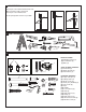
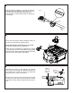
1 DOOR TYPES A. One-piece door with horizontal track only B. Sectional door with curved track A C. One-piece door without track To suit spring balanced doors up to 20m2 2 TOOLS REQUIRED 1 3 C B 2 10mm, 8mm, 4.
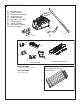
HARDWARE PROVIDED (1) (2) (3) (4) (5) (6) (7) (8) (9) (10) MT5580 opener Angled door arm Door mounting bracket Straight door arm Header bracket Stop collar, nut & bolt Pole kit adaptor Trolley assembly Idler pulley assembly Chain and joiner 1 3 2 6 5 7 POLE OPTIONS 4 9 Pole Adaptor Kit (11) 2.75m segmented pole kit NOT PICTURED 3m one piece pole 8 10 3m Chain Pack and Joiner Optional accessory 2.
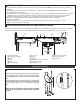
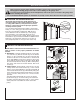
BEFORE YOU BEGIN 6 COMPLETED INSTALLATION (TILT DOOR EXAMPLE SHOWN) 1. Look at the wall or ceiling above the garage door. The header bracket must be securely fastened to structural supports. 2. Do you have a finished ceiling in your garage? If so, a support bracket and additional fastening hardware (not supplied) may be required. 3. Do you have an access door in addition to the garage door? If not, model CM1702 outside quick release accessory is required.
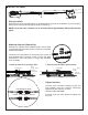
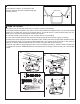
8 INSTALL THE TROLLEY AND IDLER PULLEY Slide the trolley assembly (1) onto the pole (3) taking note of the door direction arrow (fig 1). The trolley should be located midway along the pole. Insert the pole (3) into the idler pulley assembly (2) as illustrated. fig 1 DO OR 2 1 3 9 MOUNT THE ADAPTOR BRACKET AND CHAIN SPREADER Loosen the two (factory fitted) washered screws (4) from the top of the opener (approx 4mm). THESE WASHERED SCREWS MUST BE USED TO FASTEN THE POLE KIT ADAPTOR.
11 INSTALL THE CHAIN 2 1 Fitting the Chain: 3 Wrap the chain around the idler pulley (1) and desired drive sprocket (as illustrated in fig 1 and 2 below), ensuring the chain passes through the trolley assembly (3). NOTE: Locate the chain connector (2) as illustrated above approximately 300mm from the Idler pulley. Additional Step for 2750mm Pole All Chain kits supplied are for 3000mm poles. You will need to remove the pre-measured section of chain for use with the 2750mm pole option.
INSTALLATION SECTION Wear protective goggles when working overhead to protect your eyes from injury. Disengage all existing garage door locks to avoid damage to the garage door. To avoid serious personal injury from entanglement, remove all ropes connected to the garage door before installing the opener. It is recommended that the opener be installed 2.1m (7 feet) or more above the floor where space permits.
14 ATTACH POLE ASSEMBLY TO HEADER BRACKET Position opener on garage floor below the header bracket. Use packing material to protect the cover. 2 NOTE: To enable the Pole to clear sectional door springs, it may be necessary to lift opener onto a temporary support. The opener must either be secured to a support or held firmly in place by another person. Raise the pole assembly until chain pulley and header brackets come together. Join with clevis pin (1). Insert R-Clip (2) to secure.
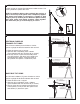
16 INSTALL VIBRATION ISOLATORS Fit the vibration isolators as indicated to help eliminate vibration often transmitted through the mounting surface. Vibration Isolator Nut Washer 17 HANG THE OPENER The opener must be securely fastened to a structural support of the garage. Three representative installations are shown. Yours may be different. Hanging brackets (1) should be angled (Figure A) to provide rigid support.
18 ATTACH MANUAL RELEASE ROPE & HANDLE Thread one end of rope (1) through hole in top of red handle so "NOTICE" reads right side up as shown (3). Secure with an overhand knot (2). Knot should be at least 25mm (1") from end of the rope to prevent slipping. Thread other end of rope through hole in release arm of the outer trolley (4). Adjust rope length so that handle is 1.8m (6 feet) above the floor. Secure with an overhand knot.
20 FASTEN DOOR BRACKET Sectional and One-Piece Door Installation Procedure: Door bracket (1) has left and right side fastening holes. If your installation requires top and bottom fastening holes use both the door bracket and door bracket plate (2) as shown. 1. Centre door bracket (with or without door bracket plate, as required) at the top inside face of door as shown. Mark holes. A. One-piece doors: locate bracket at inside face of the door 0-100mm down. B.
22 CONNECT DOOR ARM FOR (SECTIONAL DOORS) Figure 1 Pulley Trolley 200mm (8”) min. Make sure garage door is fully closed. Pull the emergency release handle to disengage the trolley. Slide the trolley assembly back 200mm from the idler pulley. Ring Fastener Figure 1. • Fasten straight door arm section to trolley assembly using the hardware provided with your opener. Clevis Pin Emergency Release Handle 7 Door Bracket Straight Door Arm Figure 2. • Bring arm section together.
23 ADJUST THE TRAVEL LIMITS ADJUSTMENT SECTION Limit adjustment settings regulate the point at which the door will stop whilst moving up or down. To set the limits: Ensure the door is in the CLOSED POSITION and the trolley is engaged (see page 11) • Turn power on • Open the door by pressing either of your pre-programmed transmitters or wireless wall button. • Run the opener through a complete travel cycle.
25 TEST THE SAFETY REVERSE SYSTEM The safety reverse system test is important. The garage door must reverse on contact with a 40mm obstacle laid flat on the floor. Failure to properly adjust opener may result in serious personal injury from a closing garage door. Repeat test once a month and adjust as needed. Procedure: Place a 40mm obstacle (1) laid flat on the floor under the garage door. Operate the door in the down direction. The door must reverse on the obstruction.
27 INSTALL WIRED DOOR CONTROLS (optional accessory) Locate wired door controls where the garage door is visible, away from door and door hardware, out of the reach of children and at a height of at least 1.5m. Serious personal injury from a moving garage door may result from misuse of opener. Do not allow children to operate the wired door controls or transmitters. Fasten the caution label on the wall near wired door controls as a reminder of safe operating procedures.
28 WIRELESS PROGRAMMING (OPTIONAL ACCESSORY) Activate the opener only when door is in full view, free of obstruction and properly adjusted. No one should enter or leave garage while door is in motion. Do not allow children to operate push button(s) or transmitter(s). Do not allow children to play near the door. The transmitters supplied with your opener are pre-programmed to your receiver in the factory.
29 INSTALLING YOUR CM128 WIRELESS WALL BUTTON INSTALL: Carefully pry open the CM128 and locate the two screw for mounting. To attach to the wall, use the two screws and wall anchors provided, if mount to plaster wall (If using a recessed wall box do not use anchors). NOTE: Tightening the wall mount screws will reduce clearance between bracket and wall. NOTE: Your CM128 Wireless wall button should be pre-programmed into your opener, you should only need to program additional units.
31 ACCESSORIES (1) Model CM844 (2) Model CM128 (3) Model C940 (4) Model C943 (5) Model C945 (6) Model 75LM 4 Channel transmitter Wireless wall button Single channel transmitter 3 Channel transmitter 3 Channel mini transmitter Illuminated door bell push button CM844 C940 CM128 2 1 C840 (7) Model C98 (8) Model C840 (9) Model C77 (10) Model CM1702 (11) Model 760E (12) Model C379 (13) Model ANT4X-1LM C1702 C77 9 8 C945 C943 3 4 75LM Max.
OPERATION OF YOUR OPENER Your opener can be activated by any of the following devices: • Wireless Wall Button (CM128). Press button down until door starts to move. • The Outside Keyswitch or Keyless Entry System (if you have installed either of these accessories). • The Transmitter. Hold the push button down until the door starts to move. Opening the Door Manually: Door should be fully closed if possible. Weak or broken springs could allow an open door to fall rapidly.
32 REPLACEMENT PARTS NOT ICE 178B0086B 091B0019 012B0905 E AS RE IL G 3A4 .8 NO RA 012B0906 083A0011-1 178B0034B 002A1659 002A1658 001A7350 012B0415 PDR30005 2.
32 REPLACEMENT PARTS 041A3261-1 (Dual Sprocket) If the supply cord is damaged, it must be replaced by the manufacturer, its service agent or similarly qualified persons in order to avoid hazard.
Troubleshooting 1. Opener doesn't operate from either door control or transmitter: • Does the opener have electric power? Plug lamp into outlet. If it doesn't light, check the fuse box or the circuit breaker. (Some outlets are controlled by a wall switch.) • Have you disengaged all door locks? Review installation instruction warnings on page 2. • Is there a build-up of ice or snow under door? The door may be frozen to ground. Remove any obstruction. • The garage door spring may be broken. Have it replaced.
CHAMBERLAIN LIMITED WARRANTY Merlin Professional MT5580P Sectional Garage Door Opener Chamberlain Australia Pty Limited / Chamberlain New Zealand Limited (Chamberlain), the manufacturer of Merlin® automatic garage door openers, is committed to manufacturing and supplying high quality goods. As part of this commitment, we seek to provide reliable service and support for our goods and are pleased to provide you, the original purchaser, with this Chamberlain Limited Warranty.