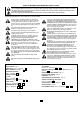
START BY READING THESE IMPORTANT SAFETY RULES These safety alert symbols mean Caution – a personal safety or property damage instruction. Read these instructions carefully. This garage door opener is designed and tested to offer reasonable safe service provided it is installed and operated in strict accordance with the following safety rules. Failure to comply with the following instructions may result in serious personal injury or property damage.
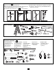
DOOR TYPES – 1 A. One-Piece Door with Horizontal Track Only B. One-Piece Door with Horizontal and Vertical Track – Special door arm (F, The Chamberlain Arm™) required. See your dealer. C. Sectional Door with Curved Track – See 20 B – connect door arm. A B TOOLS REQUIRED - D. Double-wing door – Special door arm required. See your dealer. E. Canopy door – Special door arm (F, The Chamberlain Arm™) required. See your dealer.
BEFORE YOU BEGIN / PREPARING YOUR GARAGE DOOR: 1. Look at the wall or ceiling above the garage door. The header bracket must be securely fastened to structural supports. 2. Do you have a finished ceiling in your garage? If so, a support bracket and additional fastening hardware (not supplied) may be required. 3. Depending on your door's construction, you might need a special door arm. See your dealer. 4.
PLANNING - 4 Identify the type and height of your garage door. Survey your garage area to see if any of the conditions below apply to your installation. Additional materials may be required. You may find it helpful to refer back to this page and the accompanying illustrations as you proceed with the installation of your opener. FINISHED CEILING SECTIONAL DOOR INSTALLATION Support bracket & fastening hardware is required. See page 12.
ASSEMBLY SECTION 5 – 6 1 FASTEN T-RAIL & ATTACH CHAIN SPREADER – 5 3 Place packing material under the opener to protect the opener cover. For convenience, place a support under the chain pulley bracket end of rail. Remove Styrofoam from rail end and the (2) washered screws (4) from the top of the opener. Align holes in back end of the T-rail with holes in opener (7). 2 4 Fasten the rail to the opener with the same washered screws and tighten securely.
INSTALLATION SECTION 7 – 17 Wear protective goggles when working overhead to protect your eyes from injury. Disengage all existing garage door locks to avoid damage to the garage door. To avoid serious personal injury from entanglement, remove all ropes connected to the garage door before installing the opener.
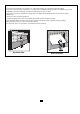
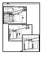
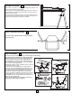
INSTALL THE HEADER BRACKET – 8 A. Wall Mount: Center the bracket (2) on the vertical guideline (1) with the bottom edge of the bracket on the horizontal line (6) (with the arrow pointing toward the ceiling). Mark either set of bracket holes (4 or 5). Do not use the holes designated for ceiling mount. Drill 4,5mm (3/16") pilot holes and fasten the bracket with wood screws (3). B. Ceiling Mount: Extend vertical guideline (1) onto the ceiling.
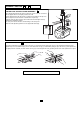
1 POSITION THE OPENER – 10 Note: A 25mm (1") board (1) is convenient for setting an ideal door-to-T-rail distance (unless headroom is not sufficient). Raise the opener onto a stepladder. Open garage door. Place a 25mm (1") board (1) laid flat on the top section of door near the centerline as shown. Rest the T-rail on the board. If the raised door hits the trolley, pull down on the trolley release arm to disconnect the inner and outer trolley sections.
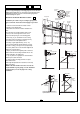
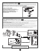
ATTACH MANUAL RELEASE ROPE & HANDLE – 13 Thread one end of rope (1) through hole in top of red handle so "NOTICE" reads right side up as shown (3). Secure with an overhand knot (2). Knot should be at least 25mm (1") from end of the rope to prevent slipping. Thread other end of rope through hole in release arm of the outer trolley (4). Adjust rope length so that handle is 1,8m (6 feet) above the floor. Secure with an overhand knot.
INSTALL THE LIGHT AND LENS – 15 Install a 40 watt maximum light bulb (1) in the socket as shown. The light will turn on and remain lit for 4-1/2 minutes when power is connected. After 4-1/2 minutes it will turn off. Replace burned out bulbs with rough service light bulbs. Apply slight pressure on sides of the lens (2) and slide tabs (3) into slots (4) in the end panel. Reverse the procedure to remove the lens.
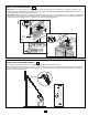
ASSEMBLE DOOR ARM AND SET LIMITS – 17 NOTE: For one-piece doors, do not connect door arm to trolley before adjusting limits. Failure to follow instructions may result in damage to door. See below. A. SECTIONAL DOOR INSTALLATION: Connect according to Figure B, then proceed to Step 18. B. ONE-PIECE DOOR INSTALLATION: Connect straight door arm (1) and curved door arm sections (2) to obtain the longest possible length with hardware (3, 4 & 5).
PROGRAM YOUR OPENER & REMOTE – 18 Activate the opener only when door is in full view, free of obstruction and properly adjusted. No one should enter or leave garage while door is in motion. Do not allow children to operate push button(s) or remote(s). Do not allow children to play near the door. Your garage door opener receiver and remote control transmitter are set to a matching code. If you purchase additional remote controls, the garage door opener must be programmed to accept the new remote code.
ADJUSTMENT SECTION 20 – 22 LIMIT ADJUSTMENT – 20 Run the opener through a complete travel cycle. Limit adjustments are not necessary when the door opens and closes completely and doesn't reverse unintentionally in the fully closed position. Situations requiring limit adjustment are listed below. Run the opener through a complete travel cycle after each adjustment. Note: Repeated operation of the opener during adjustment procedures may cause motor to overheat and shut off.
TEST THE SAFETY REVERSE SYSTEM – 22 The safety reverse system test is important. Garage door must reverse on contact with a 40mm obstacle laid flat on the floor. Failure to properly adjust opener may result in serious personal injury from a closing garage door. Repeat test once a month and adjust as needed. Procedure: Place a 40mm obstacle (1) laid flat on the floor under the garage door. Operate the door in the down direction. The door must reverse on the obstruction.
ACCESSORIES – 25 (1) Model CM842 (2) Model CM128 (3) Model C940 (4) Model C943 (5) Model C945 (6) Model 75LM (7) Model C98 (8)Model C840 (9) Model C77 (10)Model CM1702 (11)Model 760E (12)Model MDL100LM (13)Model EQL01 (14)Model 9-13-1 CM842 ACCESSORIES NOT ILLUSTRATED Double-Function Remote Control Remote Wall Button Single-Function Remote Control 3-Function Remote Control 3-Function Mini Remote Control Illuminated Door Bell Push Button Motion Detecting Control Panel Keyless Entry System The Protector Sys
CARE OF YOUR OPENER When properly installed, opener will provide high performance with a minimum of maintenance. The opener does not require additional lubrication. Limit and Force Adjustments: These adjustments must be checked and properly set when opener is installed. Only a screwdriver is required. Weather conditions may cause some minor changes in the door operation, requiring some re-adjustments, particularly during the first year of operation. Refer to the limit and force adjustments on page 13.
6. Door reverses for no apparent reason and opener light blinks for 5 seconds after reversing: Check The Protector System™ (if you have installed this accessory). If the light is blinking, correct alignment. Note: Continuously holding down the door control button will allow the door to close if the protector system is not properly aligned. The transmitter will not close the door. The opener lights will blink. 7.
REPLACEMENT PARTS 26 041A4208 Chain Styrofoam 041A3263 One-Piece Rail 178B34 Trolley Chain Pulley Bracket 1706E (1,7m) 1707E (2,3m) 1708E (2,5m) 1710E (3m) 178B69 41D3484-1 (1,7m) 41D3484-2 (2,3m) 41D3484-3 (2,4m) 41D3484-4 (3m) CE ILI NG MO UN T ON LY UP 41B4103-1 178B35B 41A4353-1 E AS RE IL G A4 RA .
SPECIFICATIONS Max. Pull Force ..............800N Rated Power...................400 W GARAGE DOOR OPENER WARRANTY Motor Type ................................Permanent split capacitor Speed .............................1500 rpm Volts ................................