
Specifications


24
COMPACT
®
NS circuit breaker
COMPACT
®
NS circuit breaker: functions and characteristics
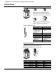
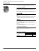
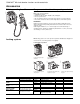
Auxiliary and alarm switches
For COMPACT
®
NSF150 to
NSJ600 circuit breakers
Changeover switches
Auxiliary switches provide remote information of the circuit breaker status and can
thus be used for indications, electrical locking, relays, etc.
Functions
■ OF (open/closed): indicates the position of the circuit breaker contacts;
■ SD (trip indication): indicates that the circuit breaker has tripped due to:
❑ An overload;
❑ A short circuit;
❑ A ground fault;
❑ The operation of a shunt trip or undervoltage trip or the "push-to-trip" button which
resets when the circuit breaker is reset;
❑ The operation of a plug-in base or chassis when attempting to withdraw the circuit
breaker in ON position;
■ SDE (fault indication): indicates that the circuit breaker has tripped due to an
overload, a short circuit or a ground fault. Resets when the circuit breaker is reset;
■ CAM (early-make or early-break function): indicates the position of the rotary
handle. Used in particular for advanced-opening safety trip devices;
■ Connected/disconnected: indicates the position of a drawout circuit breaker;
■ Switching of very low loads: all above auxiliary switches are also available in low-
level versions capable of switching very low loads (e.g., for the control of PLCs or
electronic circuits).
"Low-level" switches are not UL Listed.
Standards
Auxiliary switches comply with UL 489, CSA C22.2 No. 5.1 and IEC 947-5 Standards.
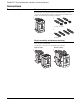
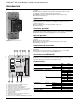
Installation
■ Functions OF, SD and SDE:
❑ The switches snap into cavities under the front accessory cover of the circuit breaker;
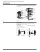
❑ For COMPACT
®
NSF150 to NSJ600 circuit breakers, one model serves for all
indication functions depending on where it is fitted in the circuit breaker.
The SDE function of a circuit breaker equipped with a thermal-magnetic trip unit
requires the SDE actuator;
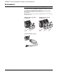
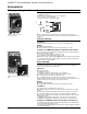
■ CAM: to be fitted in the rotary handle module. Depending on how it is installed, it
ensures either the CAO (early-break) or the CAF (early-make) function;
■ "Connected/disconnected" function: 2 parts to be fitted on the chassis and the
drawout circuit breaker.
Connections: See page 22.
044314
Accessories
Electrical ratings
UL 489 and CSA C22.2 No. 5.1 ratings
Low-level switches Regular switches
Minimum rating 1 mA—4 V 10 mA—24 V
Maximum 50/60 Hz 240 V 5 6
rating 480 V 5 6
600 V - 3
DC 48 V 2.5 2.5
125 V 0.8 0.8
250 V 0.3 0.3
IEC 947 ratings
Low-level switches Regular switches
Rated thermal current (A) 5 6
Minimum rating 1 mA—4 V 10 mA—24 V
AC DC AC DC
Utilization category AC12 AC15 DC12 DC14 AC12 AC15 DC12 DC14
(IEC 947-4)
Operational 24 V 5 3 5 1 6 6 2.5 1
current (A)
48 V 5 3 2.5 0.2 6 6 2.5 0.2
110 V 5 2.5 0.8 0.05 6 5 0.8 0.05
220/240 V 5 2 6 4
250 V 0.3 0.03 0.3 0.03
380/415 V 5 1.5 6 3
440 V 5 1.5 6 3
660/690 V 6 0.1