
Specifications

39
COMPACT
®
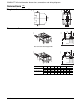
NS circuit breaker
C11 C17 C22 C23 G36 G37 G38 G39 H9 H10 H20 H23 H24 H25
NSF150/250N/H (inch) 4.05 1.67 1.14 2.99 1.41 2.83 1.61 3.93 2.36 4.72 1.10 2.87 0.35 1.47
(mm) 103 42.5 29 76 36 72 41 100 60 120 28 73 9 37.5
NSJ400/600N/H/L (inch) 6.10 1.65 1.63 4.96 1.41 2.83 2.00 5.70 3.26 6.29 1.47 4.84 0.96 1.47
(mm) 155 42 41.5 126 36 72 51 145 83 160 40 123 24.5 37.5
H26 K14 K15 L L1 L7 L8 L11 L12 L13 L14 L15 P34 P35
NSF150/250N/H (inch) 2.95 1.96 3.93 2.06 4.13 2.71 4.72 3.58 0.36 1.47 2.95 2.16 4.76 6.10
(mm) 75 50 100 52.5 105 69 120 91 9.25 37.5 75 55 121 155
NSJ400/600N/H/L (inch) 2.95 2.85 5.70 2.75 5.51 3.34 6.29 4.84 0.19 1.47 2.95 2.61 5.70 7.04
(mm) 75 72.5 145 70 140 85 160 123 5 37.5 75 66.5 145 179
P36 P37 P38 P40 P42 P43 P44 R8 R9 R14 R15 ØT6 ØT7
NSF150/250N/H (inch) 6.14 6.45 7.28 min. 9.76 min. 4.92 3.50 4.84 2.91 5.82 1.90 3.81 0.16 1.96
23.6 max. 23.6 max.
(mm) 156 164
185 min. 248 min.
125 89 123 74 148 48.5 97 4.2 50
600 max. 600 max.
NSJ400/600N/H/L (inch) 7.08 7.40 8.22 min. 10.7 min. 5.86 4.40 5.78 3.54 7.08 2.53 5.07 0.16 1.96
23.6 max. 23.6 max.
(mm) 180 188
209 min. 272 min.
149 112 147 90 180 64.5 129 4.2 50
600 max. 600 max.
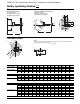
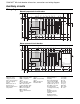
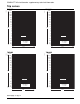
Front panel cutout
Note:
Door cutouts require a minimum distance between the center of the circuit breaker
and the door hinge point ∆ ≥ 3.93/
100
+ (h x 5).
Y
X
L12
45°
∅T6
∅T7
H24
G36
G37
∆
h
E21631
E22046
COMPACT
®
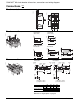
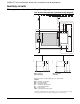
NS circuit breaker: dimensions, connections and wiring diagrams
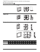
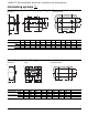
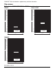
Rotary operating handles
inch
mm
Dimensions
Fixed or plug-in mounted
Cut shaft at length:
P38-4.96/
126
(NSF150/250)
P38-5.90/
150
(NSJ400/600)
Drawout mounting (telescopic shaft)
Cut shaft at length:
P38-4.80/
122
(NSF150/250)
P40-5.90/
150
(NSJ400/600)
E29163
E21630
P40
X
Z
Z
P38
X
O
I
Y
X
L14
L13
L12
H26
H25
H24
60°
60°
E21628