
Specifications

45
COMPACT
®
NS circuit breaker
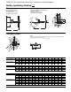
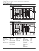
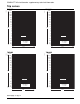
Use of the motor operator (standard wiring diagram)
82 84
SDE
81
B2 A2
A2
A4
A4
B4
B4
A1 L1
A1 L1
DP1
ON
OFF
H2
CN1 - CN 1
+
CN2 - CN 2
–
H1
RD
WH
OR
BL
GN
BK
MT
BK (1)
GN (1)
trip unit
E28273
A2 A4 B4
C1
ON OFF
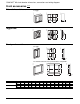
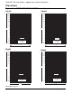
Motor operator +
undervoltage trip
Motor operator +
shunt trip
A2 A4 B4
D1
ON OFF
Mandatory manual reset after tripping due to an electrical fault.
Symbols
DP1 = protection circuit breakers
OFF = opening push button
ON = closing push button
H2 = "manual" position indication
H1 = electrical fault indication
MT = motor operator
SDE = electrical fault indication switch
(1) Jumper is supplied and must be connected by the user. Overcurrent trip switch is strongly
recommended to lock remote or automatic resetting after an overcurrent fault.
E28275
E28274
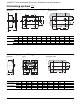
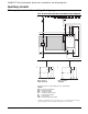
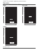
Motor operator: automatic resetting after tripping
Auxiliary circuits
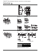
COMPACT
®
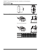
NS circuit breaker: dimensions, connections and wiring diagrams