
Specifications

57
COMPACT
®
NS circuit breaker
Interrupting ability (Y sequence)
After endurance tests and calibrations are repeated,
the circuit breaker completes an opening (O) followed
by a close-open operation (O-t-CO), with specified
current.
Examples for 3-pole breakers
Frame rating RMS Sym. Amperes
(3-pole O-and-CO)
100 A ➀ 3,000
225 A 3,000
400 A 5,000
600 A 6,000
800 A 10,000
1200 A 14,000
1600 A 20,000
2000 A 25,000
3000 A 35,000
➀ Above 250 V.
Dielectric
After testing, the circuit breaker must withstand for one minute a voltage of 1000 V
plus twice the rated voltage between:
■ Line and load terminals with circuit breaker in open, tripped and off positions;
■ Terminals of opposite polarity with circuit breaker closed;
■ Live parts and the overall enclosure with circuit breaker open and closed.
Interrupting ability
Optional tests
■ High available fault current
Circuit breakers having passed all the standard tests may have the UL Listing label
applied at higher values than the standard.
Test sequence is as follows:
❑ 200% calibration,
❑ Interrupting capacity: an opening operation followed by a close-open operation
(O-and-CO) on all poles are performed on the circuit breaker.
The power factor over 20000 A shall be 0.15 to 0.2 lagging:
❑ Trip out at 250%,
❑ Dielectric at twice the rated test voltage.
■ 100% rated
Circuit breakers having passed all the standard tests may have the UL Listing label
applied to use the circuit breaker in an enclosure when carrying 100% of its
maximum rating.
The circuit breaker is submitted to additional temperature tests performed as
standard tests, except that the circuit breaker is installed in an enclosure.
The dimensions and possible ventilations shall be recorded and shall be marked on
the circuit breaker.
Tests on accessories
Shunt trip and undervoltage trip
These devices are submitted to temperature, overvoltage, operation, endurance and
dielectric tests.
■ Overvoltage test
The device must be capable of withstanding 110% of its rated voltage continuously
without damage (this test does not apply to a shunt trip with an "a" contact
connected in series).
■ Operation
The shunt trip must operate at 75% of its rated voltage (except shunt trip devices
for use with ground-fault protection shall operate at 55%).
The undervoltage trip must trip the circuit breaker when the voltage is less than
35% and may trip the circuit breaker between 35 and 70% of its rated voltage and
shall pick-up and seal when the voltage is at 85% or more of its rated voltage.
■ Endurance
The device must be capable of performing successfully for 10% of the number of
"with current" operations of the circuit breaker.
Auxiliary and alarm switches
Auxiliary and alarm switches must be submitted to temperature, overload, endurance
and dielectric tests.
■ Overload test
The test consists of fifty operations making and breaking 150% of rated current at
rated voltage, with a 75-80% power factor in ac and non-inductive load in dc.
■ Endurance
The switch must make and break its rated current at rated voltage, with a 75-80%
power factor in ac, and non-inductive load in dc for 100% of the number of
operations "with current" for auxiliary switches, and 10% of this number for alarm
switches.
Motor operator
The motor operator shall perform the number of "without current" operations
indicated for the circuit breaker endurance tests. The first 25 operations shall be
conducted at 85% of the motor operator voltage rating.
The circuit breaker is to be tripped during these tests.
The next 25 operations shall be conducted at 110% of the motor operator voltage
rating. The balance shall be completed at rated voltage without tripping the circuit
breaker.
UL 489 test procedure
COMPACT
®
NS circuit breaker: supplementary technical information
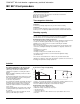
Interrupting ability (Z sequence)
A 3-pole circuit breaker rated 240, 480 or 600 V has to
complete an opening operation (O) and a close-open
operation (O-and-CO) on each pole, at rated voltage,
followed by an opening operation (O) using all 3 poles.
Examples of 3-pole circuit breakers
Frame rating RMS Sym. Amperes
Each Common
pole
O-and-CO O
100 to 800 A 8,660 10,000
1000 to 1200 A 12,120 14,000
1600 A 14,000 20,000
2000 A 14,000 25,000
3000 A 25,000 35,000