gomerlin.com.au gomerlin.co.
WARNING! START BY READING THESE IMPORTANT SAFETY INSTRUCTIONS • Failure to comply with the following instructions may result in serious personal injury or property damage. • Read and follow all instructions carefully. • The garage door opener is designed and tested to offer safe service, provided it is installed and operated in strict accordance with the instructions in this manual. These safety alert symbols mean WARNING : A possible risk to personal safety or property damage exists.
BEFORE YOU BEGIN: 1. Look at the wall and ceiling above the garage door. (The opener and header bracket must be securely fastened to structural supports.) 2. Do you have a finished ceiling in your garage? If so, a support bracket and additional fastening hardware (not supplied) may be required. 3. Do you have an access door in addition to the garage door? If not, model E1702M Outside Quick Release Accessory is required.
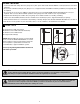
2 CARTON INVENTORY Your garage door opener and rail are packed in two seperate cartons. The tiltmaster MT100EVO opener carton contains the opener, its fitting hardware and accessories. The rail carton contains the rail and some hardware. Rails: Different length rails (2.2 m & 2.4 m) are available for different height doors, ensure you have the correct one.
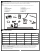
4 TOOLS REQUIRED Drill Bits 10 5 HARDWARE PROVIDED 1 (1x) 3 (4x) 2 (1x) (1) Clevis pin 80 mm (2) R clip (3) Hexagonal head screw (4) Nut M8 (5) Flat washer M8 (6) Clevis Pin (7) R clip (8) Screw ST6 x 50 mm (9) Screw ST6,3 x 18 mm (10) Wallplug 8mm 4 (4x) 5 (4x) 8 (4x) 7 (1x) 9 (8x) 6 (1x) 10 (4x) 6 COMPLETED INSTALLATION As you proceed with the assembly, installation and adjustment procedures in this manual, you may find it helpful to refer back to this illustration of a completed installation
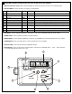
7 CONTROL PANEL (located under the cover at the rear of the opener) 1. External Accessory Power: 30 Vdc 50 mA available for universal receiver (not active in Low standby mode). 2. Terminal Block: used for external accessories (see chart below).
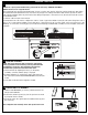
8 ASSEMBLING THE 3 PIECE SEGMENTED RAIL ASSEMBLY SECTION NOTE: For 1 piece preassembled rails, proceed to the next step “TIGHTEN THE BELT”. NOTE: Not for use on J-type tilt doors. The segmented rail is largely preassembled and consists of 3 parts. The carriage, push rod, release handle, the guide pulley and the lintel bracket with belt tensioner are in the front part (A). The seating for the drive shaft and the sprocket are in the rear part (B).
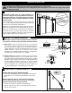
INSTALLATION SECTION Wear protective goggles when working overhead to protect your eyes from injury. Disengage all existing garage door locks to avoid damage to the garage door. To avoid serious personal injury from entanglement, remove all ropes connected to the garage door before installing the opener. 11 HEADER BRACKET POSITIONING The header bracket must be rigidly fastened to a structural support of the garage. Reinforce the wall or ceiling with a 40 mm (1-1/2") board if necessary.
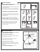
14 POSITION THE OPENER Disengage the trolley mechanism (see section “Operating the manual release”) and slide it back towards the powerhead. Secure the hanging push arm up into the rail assembly temporarily using tape or rope, to avoid a hazard. SECTIONAL DOOR OR TRACKED TILT DOOR Rail You will need a 50 mm piece of timber or similar spacer to gauge the distance between door and rail. Header 50 mm (2”) Bracket above the highest point of travel 1.Raise the opener onto support.
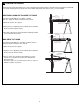
15 HANG THE OPENER The opener must be securely fastened to a sound structural support above the opener. A X fig.1 1.Postion the opener as in the previous step. Check the rail is centred over the door. Ensure the rail brackets (fig.1) is on the Powerhead end of the rail in a position as close to the opener as possible (X). 2.If mounting directly onto the ceiling, (fig.2) screw the bracket directly into a structural support on the ceiling. fig.2 fig.3 fig.4 3.
17 ATTACH DOOR ARM TO TROLLEY Make sure the garage door is fully closed. Pull the manual release cord to disengage the trolley. Slide the trolley to around 300 mm from the header bracket. 1.The straight door arm is already preassembled to the trolley. 2.Install the curved arm onto the door bracket using the Clevis pin (2) and R-Clip (3) supplied. 3.Move the straight and curved arms together and secure using two bolts and nuts provided (4). Fig. 1 Fig.
19 PROGRAM THE TRAVEL LIMITS AND FORCE SETTINGS ADJUSTMENT SECTION Travel limits regulate the points at which the door will stop when moving UP or DOWN. The travel limit buttons are located under the access cover on the rear panel (figure 1). figure 1 NOTE: This opener uses a POSITION TAB attached to the belt which activates a mechanical passpoint during the door travel. The indicator LED will blink when this occurs.
20 TEST THE SAFETY REVERSE SYSTEM The safety reverse system test is important. Garage door must reverse on contact with a 40 mm obstacle laid flat on the floor. Failure to properly adjust opener may result in serious personal injury from a closing garage door. Repeat test once a month and adjust as needed. Procedure: With door opened place a 40 mm obstacle (1) laid flat on the floor under the garage door. Operate the door in the down direction. The door must reverse off the obstacle.
23 INSTALL THE PROTECTOR SYSTEMTM (OPTIONAL) NOTE: This accessory must be used for all installations where the closing force as measured on the bottom of the door is over 400 N (40 kgf). SPECIAL NOTE: Merlin strongly recommends that The Protector SystemTM be installed on all garage door openers. IR BEAMS: By installing IR Beams, an open door is prevented from closing if a person or object is located in the beam area. If the door is already closing, it will return to the open position.
24 TIMER TO CLOSE FEATURE (TTC) Door may operate unexpectedly, therefore do not allow anything to stay in the path of the door. figure 1 The Timer to Close feature requires The Protector SystemTM (IR Beams) to be installed. Indicator LED Operation: This feature allows the door to automatically close from a fully open position after a specified time. The delay can be set from 10 to 180 seconds in 10 second increments, by using the opener control buttons.
26 INSTALL WARNING LABELS figure 1 m m B www @ service A 2 1 - r 3 F I S t ll t C ll D t For Service Call Installation Date 114A3361 RISK OF ENTRAPMENT Repeat Safety Reverse Test monthly. Door must reverse on contact with a 40mm obstacle placed on the floor. Make necessary adjustments. AUTOMATIC DRIVE: Keep away from the area of the door since it may operate unexpectedly. EMERGENCY RELEASE: To release, pull down firmly on the red handle.
28 WIRELESS PROGRAMMING (OPTIONAL ACCESSORIES) Activate the opener only when door is in full view, free of obstruction and properly adjusted. No one should enter or leave garage while door is in motion. Do not allow children to operate push button(s) or remote(s). Do not allow children to play near the door. NOTE: The transmitter(s) and wireless wall button supplied with your opener are preprogrammed by the factory.
29 USING YOUR OPENER MAINTENANCE AND CARE OF YOUR OPENER 31 REPLACE BATTERIES IN REMOTES Battery of the remote control: 1. Your opener can be activated by any of the following devices: • Opener control panel: Up and Down Buttons and Green O.S.C. • The Outside Keyswitch or Keyless Entry System (if you have installed either of these accessories). • The Remote Control Transmitter. Hold the push button down until the door starts to move. The batteries in the remote have an extremely long life.
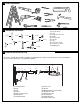
32 ACCESSORIES (1) (2) (3) (4) (5) (6) Model Model Model Model Model Model E128M E138M E950M E940M E943M E945M Wireless wall button Wireless wall button 4 Channel remote control 1 Channel visor remote control 3 Channel visor remote control 3 Channel mini remote control E138M E128M 1 E840M (7) Model E840M (8) Model C77 (9) Model E1702M (10) Model 760E (11) Model FLA24 E940M E950M 2 3 E945M E943M 5 4 760E E1702M C77 Keyless entry system The Protector SystemTM Quick release lock Outside key
34 REPLACEMENT PARTS If the supply cord is damaged, it must be replaced by the manufacturer, its service agent or similarly qualified persons in order to avoid hazard.
35 TROUBLE SHOOTING 7. Door opens but won't close: 1. Opener doesn't operate from either door control or remote: • Check The Protector System™ (if you have installed this accessory). If the light on the Beams are flashing, correct the alignment. • If opener light does not flash and it is a new installation, repeat Programming the Travel Limits. • Does the opener have electric power? Plug lamp into outlet. If it doesn't light, check the fuse box or the circuit breaker.
36 DIAGNOSTIC CHART Your garage door opener is programmed with self-diagnostic capabilities. The UP and DOWN arrows on the garage opener flash the diagnostic codes. DIAGNOSTIC CODE UP Arrow DOWN Arrow Flash(es) Flash(es) SYMPTOM 1 1 1 2 The garage door opener will not close and the courtesy light flashes. 1 3 The door control will not function. 1 4 The garage door opener will not close and the courtesy light flashes. 5 There is no door movement or motor accelerates before stopping suddenly.
37 SPECIFICATIONS - tiltmaster - MT100EVO Input Voltage...........230-240 Vac, 50 Hz Max. Pull Force ......1000 N Power .....................225 Watt Standby Power .......0.8 Watt (door fully closed) Normal Torque ........7 Nm Max door weight......130 kgs Spring balanced Max door area.........Sectional door Tilt Doors 20 m2 Motor Type........................DC gearmotor permanent lubrication Noise level ..............54 db at 1 metre Drive Mechanism Drive .......................
CHAMBERLAIN LIMITED WARRANTY Merlin® Professional Tiltmaster® MT100EVO Sectional Garage Door Opener Chamberlain Australia Pty Limited / Chamberlain New Zealand Limited (Chamberlain), the manufacturer of Merlin® automatic garage door openers, is committed to manufacturing and supplying high quality goods. As part of this commitment, we seek to provide reliable service and support for our goods and are pleased to provide you, the original purchaser, with this Chamberlain Limited Warranty.