S E R V I C E M A N U A L For all Mealstream models manufactured from January 2001 Part No. 32Z3387e Issue No.
Table of Contents Safety Code ........................................................................... 3 Product Specifications ........................................................... 4 Installation Instructions .......................................................... 5 Error Codes and Diagnostics ................................................ 6 Main Features........................................................................ 7 Electronic Controls .............................................
SAFETY CODE This manual is designed to assist engineers who have been on a recognised product familiarisation and training course run by Merrychef Limited. It has been prepared to offer technical guidance for the Merrychef Mealstream range of Combination Microwave Ovens. Please remember that it is wiser not to attempt a service task if you are unsure of being able to complete it competently, quickly, and above all safely.
PRODUCT SPECIFICATIONS Model Number: Model prefix CTM3 + Voltage + Frequency + Current + Controls Voltage Frequency Control Type 50 = 50 Hz 60 = 60 Hz 5 = Series 5 controls CD2 = Manual controls 22 = 220-230V a.c. 24 = 230-240V a.c 230-240V ac 50 Hz 13.0A Single Phase 2 Wire + Earth. 220-230V ac 50 Hz 14.2A Single Phase 2 Wire + Earth.
INSTALLATION INSTRUCTIONS Installation Instructions for Mealstream Combination Ovens Power Supply Requirements The Mealstream Series should be connected to a suitable electricity supply, which can cope with the switching-on surge that occurs with certain types of catering equipment, such as microwaves. Because of this requirement, we strongly recommend that a separate, suitably rated supply is installed for the oven.
Error Codes and Diagnostics The Mealstream Series 5 will identify some of the most common problems by flashing an error message code in the time display window. These are the error messages, and suggestions for repairing them. 1 Door not fully shut. Close door fully. 2 Possible electrical fault Door switch inoperative. 3 Magnetron overheating. Check air filters. Check location, air inlet temperature and air filters. 1 No time has been set. Set a time. 2 Invalid time has been set.
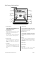
- Main Features: Mealstream Ovens a b b c f d g j e k k i h a On/Off SWITCH This is used to turn the oven On or Off. IT DOES NOT ISOLATE INTERNAL WIRING FROM THE MAINS SUPPLY. b STEAM OUTLET Allows steam and excess pressure to escape from the oven cavity. It must be kept clear. c OVEN CAVITY The oven cavity is mainly constructed from stainless steel panels. It must be kept clean.
Electronic controls: Mealstream Series 5 j i b a g h a Stage LED's b Program & Time Display c Service Indicator d Air Filter Block Indicator e Convection Pad f Power Pads g Time / Precept Pads h Temperature Set Pads i Cancel / Callback Pad j Program Pad Mealstream Ovens 32Z3387 Issue 2 f c d e Page 8
Manual controls: Mealstream CD2 a b b TEMP °C POWER % b TIME merry FKHI c d START Mealstream CD 2 e a Power Neon ( Amber ) b Control Knob c Start Push button d Cook cycle Neon ( Red ) e Heater Neon ( Amber ) Mealstream Ovens 32Z3387 Issue 2 Page 9
Procedure A - Power Output Test in accordance with BS EN 60335-2-25:1996 Annex AA This test is given in the BSI test standard for microwave ovens. It is reproduced below - not so that you can follow it, but to show you why it is impractical in normal conditions. A simplified procedure, which gives a good approximation to the BSI power output, is given in Procedure B which follows. Note: This test can only be carried out on a COLD oven.
Procedure B - Simplified Power Test You will need: A thermometer capable of reading to ±0.1°C. A Polypropylene tray approximately 200 mm x 200 mm. A measuring jug. A calculator. Water which is at a temperature of 10°C ± 2°C. 1 2 3 4 5 6 7 8 Measure 1 litre of cold water into the tray using the measuring jug. Measure the water temperature, and record it as T[s]. Place the tray on the turntable in the oven and close the door. Turn the oven on. Set the timer to 1:02. Press the “100%” pad.
Procedure D - High Voltage Capacitor Test You will need: A Digital Multi-meter (D.M.M.) A Megger or similar resistance meter using 500V d.c. WARNING: High voltages and large currents are present at the High Voltage Capacitor. It is very dangerous to work near this part when the oven is on. NEVER make any voltage measurements at the High Voltage circuits, including the magnetron filament .
PRINCIPAL COMPONENTS Mealstream Ovens Left side 1 1A 2 2A 3 3A 59 4 4A 13 5 5A 12 14 6 11 7 10 8 9 No Description SERIES 5 CD² 1 Fuse holder 30Z0231 30Z0231 1A Fuse 10 amp 30Z0168 30Z0168 2 Fuse holder 30Z0231 30Z0231 2A Fuse 10 amp 30Z0168 30Z0168 3 Fuse holder 30Z0285 30Z0285 3A Fuse 1 amp 311008 311008 4 Fuse holder 30Z0231 30Z0231 4A Fuse 13 amp 30Z0168 30Z0168 5 Fuse holder 30Z0231 30Z0231 5A Fuse 13 amp 30Z0168 30Z0168 6 Mains terminal block
Principle components: Right side 22 21 15 20 16 No 17 18 19 Description SERIES 5 CD² 15 Door arm assembly 11C0300 11C0300 16 Door hinge assembly ( RH )* 11C0166 11C0166 17 Microswitch ( Secondary ) 30Z0240 30Z0240 18 Door arm stop assembly 11C0279 11C0279 19 Door spring 520000 520000 20 Steam pipe 790046 790046 21 Steam vent guard 790061 790061 22 Temperature sensor 50E123 50E123 *See page 16 for parts Mealstream Ovens 32Z3387 Issue 2 Page 14
Principle components: Top view 60 61 23 23 24 24 25 25 26 26 27 27 28 No Description 62 SERIES 5 CD² 23 Magnetron 30Z0264 30Z0264 24 Resistor 470 R 31Z0121 31Z0121 25 HT diode 30Z0246 31Z0246 26 Capacitor 1.
Principle components: Door, roof & heater element No Description 208 240 67 Stirrer glass 40C0954 40C0954 68 Heater element 40C0949 40C0948 69 Element cover plate 790047 790047 70 Baffle ( 2 No.
Principle components: ( not shown in main views ) Door hinge assembly ( Left hand shown ) No. All models 49 Right Hand Assembly 11C0166 50 Left Hand Assembly 11C0167 51 Pin 52 Roller 53 Bolt 101825 54 Nut 80X7003 55 LH Hinge bracket 790024 56 RH Hinge bracket (not shown) 790025 No. Description All models 57 No.
INPUT WIRING DETAILS 6 Green/Yellow Blue Brown 46 48 No 47 Description SERIES 5 CD² 6 Mains Terminal Block 31Z0149 31Z0149 46 Cable Gland 31Z1070 31Z1070 47 Gland Nut 31Z1082 31Z1082 48 Mains Cable 3 Core 31Z0148 31Z0148 Mealstream Ovens 32Z3387 Issue 2 Page 18
Door Interlock Operation The door on the Mealstream oven is monitored by three microswitches. These are used in the conventional “Primary, Secondary and Monitor” switch arrangement shown below. The switches operate as follows: Door Interlock Arrangement Secondary switch L Primary switch 17 11 Power Out Power In Monitor switch 14 N 1.
Electronic Control Panel Assembly: Mealstream Series 5 34 33 29 32 31 30 No Description Series 5 29 On/Off Switch 30Z0503 30 Control Panel Assembly 11C0294 31 Logic Board 11C0213 32 Relay Board 11C0212 33 AC Ribbon connector 11M0116 34 DC Ribbon connector 11M0117 Mealstream Ovens 32Z3387 Issue 2 Page 20
Manual Control Panel Assembly: Mealstream CD² 38 39 40 40 35 29 38 44 41 29 38 44 45 41 38 No Description Series 5 35 PCB Assembly 11C0295 36 ac voltage connector 6 way 11M0116 37 dc voltage connector 10 way 11M0117 38 Red Neon 39 Timer 30Z0991 40 Potentiometer 5k 40C0892 41 Amber Neon 29 On /off switch 30Z0503 43 Panel assembly 11C0307 44 Pushbutton 31Z0349 45 Timer knob 11C0173 Mealstream Ovens 32Z3387 Issue 2 316030 316031 Page 21
Membrane Panel Circuit You will need: A Digital Multi-meter (D.M.M.) 1. 2. 3. 4. Isolate the oven from the mains supply. Remove the Logic Assembly from the Control Panel Housing. Unplug the membrane “tail” from the Logic PCB Assy. Using a D.M.M., check for continuity between the correct terminals when the pads are pressed. 5. When the panel has been tested, re-assemble and re-test the control housing.
Part Number Identification Chart: Mealstream series ovens SERIES 5 No Description Part No CD² Page No Part No Page No 1 Fuse holder 30Z0231 13 30Z0231 13 1a Fuse 10 amp 30Z0168 13 30Z0168 13 2 Fuse holder 30Z0231 13 30Z0231 13 2a Fuse 10 amp 30Z0168 13 30Z0168 13 3 Fuse holder 30Z0285 13 30Z0285 13 3a Fuse 1 amp 311008 13 311008 13 4 Fuse holder 30Z0231 13 30Z0231 13 4a Fuse 13 amp 30Z0168 13 30Z0168 13 5 Fuse holder 30Z0231 13 30Z0231 13 5a Fuse
Part Number Identification Chart: Mealstream series ovens SERIES 5 No Description Part No CD² Page No Part No Page No 29 On/Off Switch 30Z0503 19 30 Control Panel Assembly 11C0294 19 ——— ——— 31 Logic Board 11C0213 19 ——— ——— 32 Relay Board 11C0212 19 ——— ——— 33 AC Ribbon connector 11M0116 19 ——— ——— 34 DC Ribbon connector 11M0117 19 ——— ——— 35 PCB Assembly ——— ——— 11C0295 20 36 ac voltage connector 6 way ——— ——— 11M0116 20 37 dc voltage connector 10 way
CIRCUIT DIAGRAM: Series 5 Part 1 Mealstream Ovens 32Z3387 Issue 2 Page 25
CIRCUIT DIAGRAM: Series 5 Part 2 Mealstream Ovens 32Z3387 Issue 2 Page 26
CIRCUIT DIAGRAM: CD2 Part 1 Mealstream Ovens 32Z3387 Issue 2 Page 27
CIRCUIT DIAGRAM: CD2 Part 2 Mealstream Ovens 32Z3387 Issue 2 Page 28
US circuit diagram Mealstream Ovens 32Z3387 Issue 2 Page 29
Manual Corrections and Modifications Whilst every effort has been made to ensure that the information contained in this manual is accurate and complete, if you believe that an error has been made, or if you have any suggestions for how the manual could be improved, please fill in and return this form. A review of any forms returned will be made on a regular basis, and the manual will be updated if required.