Version 2.0 Merrychef 402s US Models including WAWA SE RV I CE & PA RT S M AN UA L This manual covers US models manufactured from: Version 2.0 Serial No. 000745 –001199 Version 3.0 Serial No. 001200 onwards ISSUE 6 18.03.2008 SERVICE MANUAL Version 3.0 CAUTION MICROWAVE EMISSIONS DO NOT BECOME EXPOSED TO EMISSIONS FROM THE MICROWAVE GENERATOR OR PARTS CONDUCTING MICROWAVE ENERGY 402s Ovens Pt. No.
TABLE OF CONTENTS Microwave safety precautions .................................................3 Safety code..............................................................................4 Product specifications..............................................................5 Installation instructions ............................................................6 Main features ......................................................................7– 9 Principal components: RHS...................................
MICROWAVE SAFETY PRECAUTIONS CAUTION WARNING TO SERVICE TECHNICIANS PRECAUTIONS TO BE OBSERVED BEFORE AND DURING SERVICING TO AVOID POSSIBLE EXPOSURE TO EXCESSIVE MICROWAVE ENERGY (a) Do not operate or allow the oven to be operated with the door open. (b) Make the following safety checks on all ovens to be serviced before activating the magnetron or other microwave source, and make repairs as necessary: 1) interlock operation. 2) proper door closing.
SAFETY CODE This manual is designed to assist engineers who have been on a recognised product familiarisation and training course run by Merrychef. It has been prepared to offer technical guidance for the 402s range of Ovens. Please remember that it is wiser not to attempt a service task if you are unsure of being able to complete it competently, quickly, and above all safely.
PRODUCT SPECIFICATIONS Model Number: 402S VVV F P C R TT ZZ Example 402S2086DK3GMUS Model No. EC402s 208V, 60Hz, 2P + GND supply, MenuKey Revision 3, General Market, USA Supply Voltage Freq.
INSTALLATION INSTRUCTIONS Installation Instructions for Mealstream Combination Ovens Power Supply Requirements The Mealstream Series should be connected to a suitable electricity supply, which can cope with the switching-on surge that occurs with certain types of catering equipment, including microwaves. Because of this requirement, we strongly recommend that a separate, suitably rated supply is installed for the oven. The supply for the oven should be fitted with a Type "C" or Time Delay circuit breaker.
MAIN FEATURES m a j b L f g d c e L i h k k a On/Off SWITCH h DOOR This is used to turn the oven On or Off. IT DOES NOT ISOLATE INTERNAL WIRING FROM THE MAINS SUPPLY. The door consists of a thermally insulated inner section, and an additional air gap provided by a twin skinned door front to lower the surface temperature. b MenuKey i DOOR SEAL The MenuKey System automatically changes all the cooking programs with an electronic key and allows program names to be identified.
MAIN FEATURES Electronic control panel: Version 2.0 FAN SPEED PADS PREHEAT/ COOL DOWN PROGRAM MAIN DISPLAY PANEL POWER PADS TIME/ PROGRAM PADS CANCEL PAD Cancels all timed cooking cycles, pre-programmed operations and stops the microwave energy. It does not alter the oven temperature. If the oven is hot, food will continue to cook and should be removed from the oven immediately. This pad will also cancel any incorrect operations. It will not erase programs.
MAIN FEATURES Electronic control panel: Version 3.0 MAIN DISPLAY PANEL COOL DOWN FUNCTION PADS FUNCTION PADS MenuKey 2 The MenuKey System automatically changes all the cooking programs with an electronic key and allows program names to be identified CANCEL PAD Cancels all timed cooking cycles, pre-programmed operations and stops the microwave energy. It does not alter the oven temperature. If the oven is hot, food will continue to cook and should be removed from the oven immediately.
PRINCIPAL COMPONENTS: Right Side 1 5 6 6 7 2 8 3 25A 71 25 4 70 No. Description Part No. 1 Cavity High limit Stat 30Z1024 2 Motor Start Capacitor 2µF ( Blue ) 30Z1298 3 Filter 16A 30Z1340 4 Air filter SA276 5 Stirrer motor Assembly SA288 5A Stirrer (inside cavity) SA291 5B Stirrer Gear 6 6A DV0552 Microswitch SW1 Microswitch SW2 30Z1294 Microswitch Assembly SA212 7 Door Hinge Assembly RH SA202 8 Magnetron Cooling Fan 30Z1295 25 HV Capacitor 2500V 0.
PRINCIPAL COMPONENTS: Left Side 5A 5 24 5B 6 6 9 3 25A 10 25 70 4 No. Description Part No. 3 Filter 16A 4 Air filter SA276 5 Stirrer motor Assembly SA288 5A Stirrer (inside cavity) SA291 5B Stirrer Gear 6 6A 30Z1340 DV0552 Microswitch SW3 Microswitch SW4 30Z1294 Microswitch Assembly SA212 9 Door Hinge Assembly LH SA203 10 Motor Controller 30Z1293 25 HV Capacitor 2500V 0.
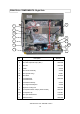
PRINCIPAL COMPONENTS: Control Box See Principal components: POWER SUPPLY 11 12 11 16 13 17 13A 14 18 15 59 72 No. Description Part No. 11 Fuse 10A HRC 30Z0217 12 Gold resistor ( 220R ) 30Z0235 13 Relay PCB Assembly 11K0004 14 Ribbon Cable 15way 11Z0298 15 Ribbon Cable 10way MenuKey 11M0117 16 Logic PCB Assembly Version 2.0 SA231 16 Logic PCB Assembly Version 3.
PRINCIPAL COMPONENTS: Back view 73 74 20 21 21 22 22 23 20 28 27 27 No. Description Part No.
PRINCIPAL COMPONENTS: Power Supply 19 3 29 31 32 30 11 34 No. Description Part No. 3 Filter 16A 30Z1340 11 Fuse 10A HRC 30Z0217 19 Cable Gland 31Z0500 19 Cable Gland Nut 31Z0499 29 Electrical Supply Lead Assembly 30 Terminal Block 31Z0447 31 Fuse 20A FLM 30Z1177 32 Fuse Holder 30A 30Z1178 34 Fuse Holder 10A 30Z0231 402s Ovens Pt. No.
PRINCIPAL COMPONENTS Cavity parts 35 36 36 38 39 40 No. Description Part No. 35* Grease Filter Cartridge Filter Housing 36 Stirrer Glass DV0492 37* Rack Support V2.5 ( Not shown ) DV0114 38 Upper Impinger plate 39 Rack V3.0 Rack V2.5 40 Lower Impinger plate SA340 SA339 SA211 DV0275 DV0158 SA266 * Parts 35 & 37 Contact Service Department KFC Accessories 62 63 60 64 61 65 Chicken Griddle SA133 No. Description Part No.
PRINCIPAL COMPONENTS External Parts Control Panel See page 15 41 52 51 42 50 43 4 52 4 Door Assembly 76 77 49 78 48 45 47 46 No. Description Part No.
PRINCIPAL COMPONENTS Electronic Control Panel Assembly Version 2.0/2.5 & WAWA 54 55 53 56 Version 3.0 57 58 66 54 53 *Note: On Ovens with Serial No.s before 000745 ( WAWA Models) External Panels Item 51 is only available to special order. 67 68 58 No. Description Part No. 53 MenuKey Dust Cover DV0052 54 Power switch (On/Off) 30Z1318 55 GM Membrane Version 2.0 & 2.5 DV0055 Membrane WAWA version DV0192 56* Front Panel Version 2.0 DV0036 57 Display Assembly & Header Version 2.
Part number identification chart 1 Ref. No. Description Part No.
Part number identification chart 2 Ref. No. Description Part No.
PROCEDURE FOR MICROWAVE EMISSION TEST (1) Warning Check for radiation emission after servicing. Should the emission be more than 4mW/cm² Inform Merrychef service centre immediately. After repairing or replacing any radiation safety device, keep a written record for future reference, as required by D.H.H.S. and Health and Welfare Canada regulation. This requirement must be strictly observed.
PROCEDURE FOR MICROWAVE EMISSION TEST (2) • Readings must be below 4mW/cm². If a level greater that 4mW/cm² is observed, this should be reported to Merrychef Service Division immediately. • In any case, notes should be kept of the leakage that is observed. In terms of level and position on the oven. This should be kept with the service documentation. Test for microwave leakage at all points marked with a Control Panel Door Perimeter Door Perimeter Rear Cover/ vents 402s Ovens Pt. No.
PROCEDURE FOR POWER OUTPUT MEASUREMENT The power output specification 1500W on this model is established under IEC 705 standard method. This method is only workable in Laboratory controlled conditions. An approximate method is as follows: Ensure the oven is cold before commencing the test Changing the Oven Profile In order to carry out the test the oven PREHEAT must be set to OFF[ V3.0 ] or 0ºF[ V2.0 ] to switch off the convection heaters and the Manual controls must be set to ON [ V3.
PROCEDURES FOR PRINCIPAL COMPONENTS TEST (1) 1. Power Transformer Test You will need: A Digital Multi-meter (D.M.M.) A Megger or similar resistance meter using 500V d.c. WARNING: High voltages and large currents are present at the High Voltage Capacitor. It is very dangerous to work near this part when the oven is on. NEVER make any voltage measurements at the High Voltage circuits, including the magnetron filament.
PROCEDURES FOR PRINCIPAL COMPONENTS TEST (2) ( High Voltage Capacitor Test continued, ensure steps 1-4 on previous page have been completed) Between Terminals Pass if approximately 10 MΩ Between Terminals and Case Pass if open circuit 5. Using a Megger, test the insulation resistance between the terminals and the case. Between Terminals and Case Pass if over 100 MΩ 3. High Voltage Rectifier Test You will need: A Megger or similar resistance meter using 500V d.c.
PROCEDURE FOR DOOR INTERLOCK ADJUSTMENT AND TEST 1 The door on the 402s oven is monitored by four microswitches. Three are used in the conventional “Primary, Secondary and Monitor” switch arrangement shown below and the fourth sends a signal to the Logic PCB. The switches operate as follows: Door Interlock Arrangement: Switches shown in Door Closed position LHS RHS L1 Power In Primary switch Secondary switch Power Out Monitor switch Logic PCB L2 1.
PROCEDURE FOR DOOR INTERLOCK ADJUSTMENT AND TEST 2 It is vital that the microswitches are adjusted to the correct position. There are two sets switch assemblies located either side of the oven. The interlocks ensure that the oven will not operate microwave with the door open. WARNING Before adjusting the microswitch assemblies ensure that the oven has been isolated from the electrical supply.
PRINCIPAL COMPONENTS: Hot Air Motor & Controller 1 Convection and Fan Speed Control The convection heat is provided by 5 elements located in the hot box at the rear of the oven cavity. The hot air from the hot box passes over catalytic converters and is circulated into the bottom and top of the cavity through the impinger plates. It returns through the removable grease filter at the back of the cavity and into the fan.
PRINCIPAL COMPONENTS: Hot Air Motor & Controller 2 Motor Controller Provides an AC, 3-phase switched mode drive to the convection motor and is controlled by a 0 - 10 Volt signal from the logic board. This allows the motor to be adjusted from approximately 1500 rpm to 7000 rpm in steps of 5%.
CIRCUIT DIAGRAM: Issue 16 402s Ovens Pt. No.
Trouble-Shooting Guide Is the problem Food Quality or Fundamental Operational Issue? Food Quality Fundamental Standard Food Quality Checks Standard Electrical Checks • Check that the PREHEAT temperature is set correctly. See User Manual. • Check that the food being cooked has been stored at the correct temperature. • Check that the correct program is being used. • Check that oven is connected to an Electricl Power supply and that any trip that supplies the unit is not switched off.
No Display Is Logic PCB Active ? See D7 LED OFF OFF ON Is Relay PCB Active see D27 ON Check cable from logic PCB to display is in place and no obvious wires are disconnected or shorted. Still Have a problem? Check 15 Way Ribbon Cable between Logic and Relay PCB. Still Have a Problem? Using spare display connect to Logic PCB Still Dead Spare Display works Replace Display Check Connection Output at Aux Transformer.
Cold Food Check Convection Temperature control OK NO Possible Temperature Sensor Fault. Assuming sensor Ok then make sure door Light on logic PCB is on when door closed. If this is working then replace Logic PCB. Check Current using clip on current meter through F7 and F8. When running Microwave only. You will need to reset the pre-heat temperature to 0 and enable manual control via the profile setting. Make sure that there is a water load in the cavity.
Cavity Sensor Error Are there any Signs of Cavity Fire YES Report to Management and Make Investigation NO Check Temperature Sensor Resistance OK NOT OK Re-Start Oven Activate Pre-heat Is Led D19 on relay PCB ON Yes LED is on. Check Heater Elements Replace if necessary N Check door Switch LED on logic PCB LED is on Is the temperature display saying too hot ? N Check the Door Interlock Switch. Check The interconnecting lead to the logic PCB.
Magnetron / Overheat issues Remove and Clean Air Filters. If Dirty—Advise operating staff of the need for this to be carried out on regular basis. See User Manual Still have a problem. Check Location of oven is away from any major heat sources. Recommend re-location if necessary Location fine and still have a problem. Check cooling fan operation. Make sure there is Noticeable airflow from air vents at the rear of the oven. If Not investigate and replace cooling fan if necessary.
APPENDIX 1: TEMPERATURE SENSOR RESISTANCE DATA Temperature Sensor Resistance Temp °F Temp °C Min. Rate kΩ Standard Rate kΩ Max. Rate kΩ 212 100 11.490 13.060 14.810 302 150 2.803 3.161 3.434 392 200 0.950 1.000 1.050 482 250 0.3572 0.3865 0.4171 R(200)°C = 1 kΩ ± 5% Note: These resistances will only be apparent in a stable cavity temperature as the sensor has a slow response time. 402s Ovens Pt. No.
APPENDIX 2: MenuKey Version 2.0 models The MenuKey System automatically changes all the cooking programs on the oven from a pre-programmed electronic key. Do not remove the key during download sequence as this could corrupt the data on the key To change the menus on the oven: 1 Ensure the power switch is OFF. 2 Lift the MenuKey cover in the top front panel of the oven and put the key in the slot. MENUKEY2 3 With the key still in place switch the power switch ON.
APPENDIX 2: MenuKey Version 3.0 models The MenuKey System automatically changes all the cooking programs on the oven from a pre-programmed electronic key. To change the menus on the oven: WARNING Downloading from a MenuKey will clear all the existing programs Do not remove the key during download sequence as this could corrupt the data on the key MENUKEY2 Check that the key has the correct number/code for the programs you want to load into the oven memory 1 Ensure the power switch is OFF.
APPENDIX 3: Cool Down Procedure To cool down and clean a hot oven Action EC402s V2.0 EC 402s V3.
APPENDIX 3: CLEANING: 1 For the oven to operate at peak efficiency, the cavity, door and air filters and grease filter must be kept clean. A daily cleaning routine will ensure that you comply with the required hygiene standards and will help to maintain and prolong the efficiency of your oven. Follow the SAFETY INSTRUCTIONS at the beginning of this manual.
APPENDIX 3: CLEANING: 2 • ALWAYS switch off at the electrical supply and allow oven to cool before cleaning • CAUTION: Allow the oven and accessories to cool before commencing cleaning WARNING: DO NOT use caustic cleaners on any part of the oven or oven cavity as it will cause permanent damage to the Catalytic Convertors Equipment: Merrychef oven cleaner, Merrychef Oven Protector, heat proof gloves, protective rubber gloves, non–abrasive nylon scrub pad, cleaning towel and cloths, eye protection and dust ma
APPENDIX 4: Recommended spares lists Part Number Description USA Qty Unit First Aid Kit Service Kit 1-5 Ovens 5-50 Ovens 50-100 Ovens Piece Qty for 600 Ovens 2 11H0010 HT DIODE ASSY 2 EA 2 2 6 12 72 11K0002 LOGIC BOARD MAIN ASSY (V2 & V2.
APPENDIX 4: Recommended spares lists Part Number Description USA CONT.
APPENDIX 5: LOGIC PCB Connection Points and key features. Spare input not used Display Connecter Temp Calibration Relay PCB 15 way Connecter Door Switch IP Door switch Indicator ON when door closed Remote data point MenuKey Sockect Connector Program memory storage. May be exchanged with New PCB if PCB replaced. Motor speed controller Membrane panel connector 402s Ovens Pt. No.
APPENDIX 5: Relay PCB Connection Points and key features. D15 Magnetron active Cavity Temperature Sensor Input D16 Magnetron soft start D19 Heater ON Magentron Overheat sensor Inputs D20 LED ON when power is on OFF when Microwave is operated. Connector To Logic PCB U1 Ambient air temperature sensor Display Fuse Fuse Not Used AC input from Aux Transformer Piezo sounder output 402s Ovens Pt. No.
APPENDIX 6: Engineering Test Settings Engineering Test Settings - Changing the Oven Profile In order to carry out an oven test procedure the oven PREHEAT must be set to 0ºF/OFF to switch off the convection heaters and the Manual controls must be enabled. When the test is completed the oven must be returned to its original settings or the appropriate MenuKey can be used to reset the oven automatically. To set the PREHEAT temperature to 0ºF/OFF 402s Version 3.0 models 402s Version 2.0/ 2.5 1.
APPENDIX 7: Firmware revision guide. As a result of on-going changes / upgrades to the 402s Oven, this Appendix has been produced stating the following: 1.0 An overview of the control system for a 402s. 2.0 How to check your Firmware version 3.0 How to check your hardware fitted 4.0 CODEKEY firmware upgrade 5.0 MenuKey2 download CODEKEY Reference ( See Table 1 for abbreviations description) Version 3 Part No. 31Z7066 3.0LD 402s Large Display UK/EU (FO / EMD) Part No. 31Z7068 3.
2.0 How to check your Firmware Version: 2.1 Power up the oven and verify the Firmware version that is loaded into the oven. OVEN INFORMATION Oven On Time: Magnetron On Time: Door Operations: Software Version: MenuKey Code: MenuKey Checksum 00028 Hours 00000 Hours 00049 4.
3.0 How to check your hardware fitted: 3.1 Remove the oven lid to reveal the Logic PCB. See Table 2a below Hardware fitted against PCB visual TABLE 2A SSR PCB Visual Check Supports Oven Upgrade to V3 Mag Detect Allowable Version / Firmware Revision 1 ONLY ON V2 ovens 4.4SD Device secured to plate No pin strip ON V2.5 ovens 4.4SD or higher Revision 2 Device free standing ON V3 Ovens 3.
Hardware fitted against PCB visual TABLE 2A SSR PCB Visual Check Supports Oven Upgrade to V3 Mag Detect Blue jumper fitted Allowable Version / Firmware ON V2.5 ovens 4.4SD Revision 3 ON V3 ovens 3.0LD or higher Optics board fitted SSR lead SSR would be fitted if lead is present on PCB ONLY ON V3 ovens 3.0LD or higher Fibre Optics Board + leads fitted TABLE 2b: Hardware Upgrade Technical Bulletin Required V2 oven V2.
4.0 CODEKEY Firmware upgrade Procedure: Before commencing an oven Firmware upgrade ensure the oven is switched off 4.1 Insert the appropriate CODEKEY (see Matrix 01 on page 2) into the Menukey receptacle on the control panel. Lift cover to insert CodeKey into Menukey receptacle. Oven power switch 4.2 Warning: During the next step the display will be blank for approximately 1 minute. DO NOT REMOVE THE CODEKEY/ DO NOT TURN THE OVEN OFF this will damage the logic board.
4.3 To confirm a successful download check that the Software Version on the oven and the CODEKEY fob Label are the same. OVEN INFORMATION Oven On Time: Magnetron On Time: Door Operations: Software Version: MenuKey Code: MenuKey Checksum 00028 Hours 00000 Hours 00049 4.3LD 002 F076 EXIT>> Software Version CODEKEY Fob Label Software: 4.3LD Date: 00/00/07 CS: 0x9C71 4.4 Press exit and remove and retain the CODEKEY. 5.