
Service manual

402s Ovens Pt. No. 32Z3522 Issue 6
26
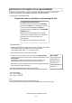
WARNING
Before adjusting the microswitch
assemblies ensure that the oven
has been isolated from the
electrical supply.
Please note the terminals on the
microswitches remain live when
the oven is switched off, so
complete isolation is essential.
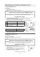
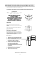
Objective
With a 1mm spacer located as shown, both
switches on both sides should be activated/ closed
position.
With a 5mm spacer located as shown SW2 and
SW3 should be open.
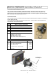
Method of adjustment.
By loosening the four screws on each mounting
bracket the microswitch assembly can be raised or
lowered and thereby the switches can be made to
operate at different door positions.
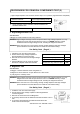
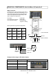
Procedure.
1. Isolate the oven from the Electrical supply.
2. Place a 1mm spacer between the cavity face
and the door seal as shown.
3. Working on the right hand side, adjust the
bracket so the SW2 ‘just’ operates.
4. Working on the left hand side, adjust the
bracket so that SW3 ‘just’ operates.
5. Remove the 1mm spacer and then place a
5mm spacer in the same position.
Check that SW2 and SW3 are open circuit and
not operated.
6. Repeat the steps above to ensure the setup is
correct.
7. Ensure that all the screws are tightened.
8. Reconnect the electrical supply.
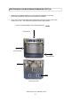
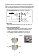
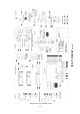
PROCEDURE FOR DOOR INTERLOCK ADJUSTMENT AND TEST 2
It is vital that the microswitches are adjusted to the correct position. There are two sets
switch assemblies located either side of the oven.
The interlocks ensure that the oven will not operate microwave with the door open.
Spacer
Door seal
Door