SERVICE MANUAL Part No. 32Z3311 Issue No.
Table of Contents Safety Code ...........................................................................3 Product Specifications ...........................................................4 Principles of Operation ..........................................................5 Installation Instructions ...................................................... 6-7 Error Codes and Diagnostics.................................................8 Main Features.............................................................
SAFETY CODE This manual is designed to assist engineers who have been on a recognised product familiarisation and training course run by Merrychef Limited. It has been prepared to offer technical guidance for the Merrychef Mealstream 401 range of Combination Microwave Ovens. Please remember that it is wiser not to attempt a service task if you are unsure of being able to complete it competently, quickly, and above all safely.
Product specifications ELECTRONIC CONTROLS Model Number: RMC1003 + Voltage + Frequency + Current + Controls + Phase For example: RMC100345XE52 Model Mealstream 401, 230-240V, 50Hz, 30A, Series 5 Controls, Twin Phase Model prefix RMC1003 Voltage 2 = 220-230V a.c. 4 = 230-240V a.
Principles of operation Mealstream 401Ovens 32Z3311 Issue 8 Page 5
Installation instructions Positioning the Oven In order to maintain adequate ventilation for air intake and exhaust, and to allow access for cleaning filters, you must allow a minimum of 50mm clearance at the sides and rear of the oven, and at least 150mm above. Air intake temperature should not exceed 35°C. Excessive temperature will lead to reduced operating duty cycle or premature ageing of internal components. NEVER Install an oven above fryers, grills, griddles or any other major heat source.
Electrical installation: WARNING: This appliance must be earthed. Failure to do so may result in electric shock and death All models ( 30A ) must be connected to a separate electrical supply rated at WARNING 30 Amps by a qualified and approved electrician. A suitable 30 amp rated isolating switch with a 3mm contact gap on both poles should be fitted for each oven installed.
Error codes and diagnostics The Mealstream EC401 will identify some of the most common problems by flashing an error message code in the time display window. Error Message Possible Cause Service 1 Door not fully shut Close door fully.
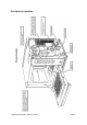
Main features a b d c e p g f h q n i b l rear view of Oven k m a STEAM OUTLET Allows steam and excess pressure to escape from the oven cavity. It must be kept clear. b AIR OUTLET Warm air is vented here. It must be kept clear. c TRAY HANDLE RESTS There is one on each side of the oven for convenient storage of the tray handle. d BAFFLE PLATE Forms the inside rear of the oven and covers the hot air circulation fan. Removable for cleaning by unscrewing the four wing nuts which hold it in place.
Electronic controls: Mealstream EC401 a Stage LED's b Service Indicator a c Air Filter Block Indicator b d Operator error indicator c e Program Display d f Temperature Set Pads g Time / Program Number Pads h Cancel/ Callback Pad i Program Pad j Convection Pad k Microwave power Pads l On/Off switch e m f g MenuKey socket i 0 175 200 225 250 275 1 2 3 4 5 6 7 8 9 P 0 C 25% 50% h j k 75% l m 100% Starbucks model Mealstream 401Ovens 32Z3311 Issue 8 P
Manual controls: Mealstream RD401 a b a Temperature Amber Neon b Temperature Control c Microwave Power Control d Timer e Start Pushbutton f Cook cycle Red Neon g Power Amber Neon h On/Off switch c d e f g h Mealstream 401Ovens 32Z3311 Issue 8 Page 11
Procedure A - Power Output Test In accordance with BS EN 60335-2-90 This test is given in the BSI test standard for microwave ovens. It is reproduced below - not so that you can follow it, but to show you why it is impractical in normal conditions. A simplified procedure, which gives a good approximation to the BSI power output, is given in Procedure B which follows. Note: This test can only be carried out on a COLD oven.
Procedure B - Simplified Power Output Test You will need: A thermometer capable of reading to ±0.1°C. A Polypropylene tray approximately 200 mm x 200 mm. A measuring jug. A calculator. Water which is at a temperature of 10°C ± 2°C. 1 2 3 4 5 6 7 8 Measure 1 litre of cold water into the tray using the measuring jug. Measure the water temperature, and record it as T[s]. Place the tray on the turntable in the oven and close the door. Turn the oven on. Set the timer to 1:02.
Procedure D - High Voltage Capacitor Test You will need: A Digital Multi-meter (D.M.M.) A Megger or similar resistance meter using 500V d.c. WARNING: High voltages and large currents are present at the High Voltage Capacitor. It is very dangerous to work near this part when the oven is on. NEVER make any voltage measurements at the High Voltage circuits, including the magnetron filament .
Door interlock operation The door on the Mealstream 401 oven is monitored by four microswitches. Three of these are used in the conventional “Primary, Secondary and Monitor” switch arrangement shown below, while the fourth is a low-voltage switch linked directly to the control circuitry. The switches operate as follows: 56 Door Interlock Arrangement Top RH 57 L Power In Bottom Inner Top LH 55 Bottom Outer 58 Power Out N 1.
Principal components: casework 105 96 104 105A MC3134 9 Handle Hanger RCK6319 RMC6773 10 Rubber Foot RMC6104 MC3120X01 11 Front Lower Panel MC3047 Top Plate RMC6759E 12 Lower Trim MC3122 5 Exhaust Gallery RMC73372 96 PCB Retainer LH 40H0083 6 Rear Panel MC3129 104 PCB Retainer RH 40H0084 7 Air Filter MC3155 105 Side Trim LH MC31211 8 Side Panel (R/H) MC3133 105A Side Trim RH MC31212 1 Side Panel (L/H) 2 Ferrit 3 Upper Trim 4 Mealstream 401Ovens 32Z3311 Issu
Door mechanism 13 Door Stay (R/H) 14 Hinge Body 15 Hook (A) RMC66171 16 Hook (B) RMC66172 17 Door Spring (B) 18 Hinge Body (L/H) 19 Door Spring (A) MC3067 20 Door Stay (L/H) MC3046 21 Microswitch Guide 40H0076 22 Solid Door Assy Black 11H0071 22 Solid Door Assy Silver 11H0031 Mealstream 401Ovens 32Z3311 Issue 8 MC3040 MC30121X02 MC3068X01 MC30122X01 Page 17
Oven cavity components and hot air system 23 Turntable Disc RMC7340X01 31 Gearbox 24 Baffle Plate Bolt 25 Baffle Plate 26 Fan Fixing Cap 27 MC3216 CP30326 32 Shaft MC3018 33 Cooling Fan RCK7617 34 Motor Bracket Fan MC3111 35 Cushion Rubber RCK8273 28 Partition Plate 11H0007 36 Motor Fixing Screw CP30310 29 Cavity Sealing Glass RMC7043 37 Hot Air Motor 30 Oven Body RMC7391X01 RMC7310 RMC7307X01 MC3110 MC3013 Mealstream 401Ovens 32Z3311 Issue 8 Page 18
Oven door assembly Solid door assembly, Silver 11H0031 Solid door assembly, Black 11H0071 22 Solid Door Assy.
Magnetron and door interlock components Model RMC1003__EE5 Model RMC1003__XE5 54 Door Switch Bracket 40H0023 62 Inlet Duct 55 56 57 58 30Z0240 30Z0240 30Z0240 30Z0240 63 Magnetron 30Z0264 64 Magnetron Cut-out 30Z0088 59 Microswitch Insulator 31Z0115 66 Blower Assembly MC3141 60 Outlet Duct MC3037 67 M3 x 25 Pan Head Pozi 31Z3093 61 Foam Tape 31Z0042 68 M3 x 30 Pan Head Pozi 31Z3118 Primary Microswitch Low Voltage Microswitch Secondary Microswitch Monitor Microswitch Mealstream 401Oven
Magnetron and door interlock components Model RMC1003__XX5 Model RMC1003__XX52 129 133 128 128 54 Door Switch Bracket 40H0023 64 Magnetron Cut-out 55 Primary Microswitch 56 Low Voltage Microswitch 57 Secondary Microswitch 30Z0240 30Z0240 30Z0240 65 Switch Bracket 59 Microswitch Insulator 31Z0115 128 Cooling Fan 220/240V 30Z1128 60 Outlet Duct MC3037 128 Cooling 30Z1190 61 Foam Tape 31Z0042 129 Turntable Motor 63 Magnetron 30Z0264 Mealstream 401Ovens 32Z3311 Issue 8 30Z0088 RMC7101X01
Major electrical components *Not RMC1003__XX5/XX52 See Page 23 64 Magnetron Overheat Switch 30Z0088 74 Temperature Sensor 50E123 69 Cavity Overheat Switch 30Z1031 75 HV Diode Assembly 11H0010 70 Bridge Rectifier (__EE only) 71 No. 8 Screw 341520 31Z3107 72 M5 Screw 101825 76 HT Capacitor 1.1µ (50Hz) 30Z1077 76 HT Capacitor 0.88µ (50Hz) 30Z1075 76 HT Capacitor 0.6µ (60Hz) 30Z0385 30Z0377 73 220V Heating Element 40H0077 76 HT Capacitor 0.
Input wiring, filters and fuses Model RMC1003__XE5, XD Model RMC1003__EE5, CD2 Green / Yellow Green / Yellow Blue Blue Brown Brown 111 112 112a 115 111 111 Mains Input Block 31Z0328 112 Cable Gland 31Z1070 112A Cable Gland Nut 113 Input Cable Assembly 115 XE5 Input Cable Assembly 116 Strain Relief Grommet 116 113 31Z1082 31Z0220 302030 31Z1036 82 78 79 81 77 80 79 81 77 Microwave Mains Filter 16A 30Z0997 78 Heater Mains Filter 16A 30Z0997 79 Fuse Cover 20Z1080 80 Fuse 10A HR
Input wiring details: Model RMC1003__XX5, XX52 Green / Yellow Green / Yellow Blue Blue Brown L2 111 112 112a L1 115 111 111 Mains Input Block 31Z0328 112 Cable Gland 31Z1070 112A Cable Gland Nut 113 Input Cable Assembly 31Z1082 31Z0220 115 XE5 Input Cable Assembly 116 Strain Relief Grommet 302030 31Z1036 78 77 79 82 81 80 79 81 77 Microwave Mains Filter 16A 30Z0997 78 Heater Mains Filter 16A 30Z0997 79 Fuse Cover 20Z1080 80 Fuse 10A HRC 30Z0217 81 Fuse Holder 1” 30Z0231 82 Fuse
HT Components: RMC1003__EE5/ XE5 75 HV Diode Assembly 76 HT Capacitor 1.1µ 11H0010 (50Hz) 30Z1077 76 HT Capacitor 0.88µ (50Hz) 30Z1075 76 HT Capacitor 0.6µ (60Hz) 30Z0385 76 HT Capacitor 0.
HT & principle components: Models RMC1003__XX5, RMC1003__XX52 Right side 102 130 132 128 90 90 76 76 76* HT Capacitor 0.88µF (50Hz) 30Z1075 76* HT Capacitor 0.6µF (60Hz) 30Z0385 76* HT Capacitor 0.
Electronic control panel assembly 100 110 102 98 101 99 107 95 108 107 103 0 175 200 225 250 275 1 2 3 4 5 6 7 8 9 P 0 C 25% 50% 110 75% 100% 107 100 97 109 Membrane Panel Menukey (Blue) Model 97 131 95 Membrane Assy 97 On/Off Switch 98 Logic Assy.
Manual control panel assembly 105A 123 124A 121 124B 124C 124D 122 125 105 126 97 123 97 On/Off Switch 30Z0503 104 PCB Retainer RH 40H0084 105 Side Trim LH MC31211 105A Side Trim RH MC31212 106 M5 Flat Washer 31Z5004 121 PCB Assembly 11H0027 122 Timer 30Z0991 123 Amber Neon 316031 124A Control Knob Black 313020 124B Control Knob Skirt Red 313160 124B Control Knob Skirt Blue 31Z1216 124C Control Knob Cap Red 313220 124C Control Knob Cap Blue 31Z1217 124D Control Knob
Membrane panel circuit You will need: A Digital Multi-meter (D.M.M.) 1. Isolate the oven from the mains supply. 2. Remove the Logic Assembly from the Control Panel Housing. 3. Unplug the membrane “tail” from the Logic PCB Assy. 4. Using a D.M.M., check for continuity between the correct terminals when the pads are pressed. 5. When the panel has been tested, re-assemble and re-test the control housing.
Part number identification chart 1 1 SIDE PANEL (L/H) MC3134 41 INSULATION PANEL 2 FERRITE 3 RMC6773 42 DOOR REINFORCEMENT UPPER TRIM MC3120X01 43 DOOR FRAME (B) MC3055 4 TOP PLATE RMC6759E 44 INSULATION WRAP 32Z0001 5 EXHAUST GALLERY RMC73372 46 DOOR BASE SILVER MC3031KX04 6 REAR PANEL MC3129 47 DOOR COVER MC3064 7 GREASE FILTER MC3155 48 PLATE - DOOR SWITCH MC3056 8 SIDE PANEL (R/H) MC3133 52 PACKING (B) MC3065 9 HANDLE HANGER RCK6319 53 DOOR REAR PLATE 1
Part number identification chart 2 77 78 M’WAVE MAINS FILTER 16A HEATER MAINS FILTER 16A 30Z0997 30Z0997 117 80mm Axial Fan 310010 121 PCB Assembly 11H0027 79 FUSE COVER 20Z1080 122 Timer 30Z0991 80 FUSE 10A HRC 30Z0217 123 Neon Amber 316031 81 FUSE HOLDER 1” 30Z0231 124A Control Knob Black 313020 82 FUSE 13A ANTI-SURGE 30Z0168 124B Control Knob Skirt Red 313160 88 HT TRANSFORMER TOP MC3127 124B Control Knob Skirt Blue 31Z1216 89 HV LEAD ASSEMBLY 11H0025 124C Contr
Circuit diagram: RMC 1003__5 EE & RMC 1003__XE Mealstream 401Ovens 32Z3311 Issue 8 Page 32
Circuit diagram: RMC 1003__XX5 (Single Phase) Mealstream 401Ovens 32Z3311 Issue 8 Page 33
Circuit diagram: RMC 1003__XX52 (Twin Phase) Mealstream 401Ovens 32Z3311 Issue 8 Page 34
APPENDIX 1: MenuKey Download Procedure The MenuKey™ System automatically changes all the cooking programs on the numbered icon pads with the turn of a key. To change the menus on the oven: 1 Ensure the power switch is off. 2 Lift the MenuKey cover in the front panel of the oven and put the key in the keyhole Turn the key clockwise to the stop ( ¼ turn ). Do not remove the key at this stage. 3 Switch the power switch on.
APPENDIX 2: Cleaning Procedure For the oven to operate at peak efficiency, the cavity, door and air filters must be kept clean. A daily cleaning routine will ensure that you comply with the required hygiene standards and will help to maintain and prolong the efficiency of your oven. Follow the SAFETY INSTRUCTIONS at the beginning of this manual.
Manual corrections and modifications Whilst every effort has been made to ensure that the information contained in this manual is accurate and complete, if you believe that an error has been made, or if you have any suggestions for how the manual could be improved, please fill in and return this form. A review of any forms returned will be made on a regular basis, and the manual will be updated if required.