
Users Manual Part 1


6 / 29
INSTALLATION AND OPERATING INSTRUCTIONS DRAFT FOR OEM USE ONLY
© 2019 Mertik Maxitrol GmbH & Co. KG, All Rights Reserved.
CAUTION: Further tightening will damage the plastic sleeve in
the brass interrupter block and will cause a short in the circuit.
NOTE: Do not over-torque or under-torque the interrupter
block to achieve a specic slot alignment.
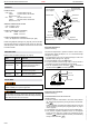
2.
Slide spade connectors into plastic insert (see gure 10, page 6).
3. Slide plastic insert with spade connectors into the brass inter-
rupter block until it snaps (see gure 11, page 6).
4. While holding the interrupter block with a wrench, thread the
thermocouple into the female end of the interrupter block ¼ –
½ turn beyond nger tight (see gure 12, page 6).
IGNITION CABLE
AMBIENT TEMPERATURE RANGE
CSA: Ignition Cable: 302 °F
CE: Ignition Cable: 150 °C
CAUTION: Damage and / or interference will occur to the GV
electronic system if the ignition cable (high voltage) is not sepa-
rated from other GV system wiring.
NOTICE
Do not damage the ignition cable while attaching it to the igni-
tion electrode. When the cable is in place, avoid contact with
sharp objects or edges.
With cables longer than 900 mm, avoid contact with metal parts,
as this could decrease spark.
RECEIVER
AMBIENT TEMPERATURE RANGE
CSA: Receiver without internal batteries: 32 °F to 176 °F
Receiver with internal batteries: 32 °F to 131 °F
CE: Receiver without internal batteries: 0 °C to 80 °C
Receiver with internal batteries: 0 °C to 55 °C
RADIO FREQUENCY
CSA: 918.0 MHz for U.S. (FCC), Canada (ISED), New Zea-
land (RNZ) and Australia (ACMA) (handset, receiver)
CE: 868.1 MHz for Europe (handset, receiver)
(see general radio frequency information on page 4.)
POWER CONSUMPTION (STANDBY)
CSA + CE: B6R-R8(A)... : 0.7 mW
POWER CONSUMPTION (NOMINAL)
CSA + CE: B6R-R8(A)... : 0.8 mW
POWER CONSUMPTION (MOTOR TURN)
CSA + CE: B6R-R8(A)... : 0.25 W
POWER CONSUMPTION (IGNITION)
CSA + CE: B6R-R8(A)... : 3.0 W
POWER SUPPLY
Receiver: 4 x 1.5 V “AA” (quality alkaline recommended)
An AC mains adapter may be used instead of batteries.
NOTICE
Only the Mertik Maxitrol AC mains adapter (see gure 5, page
3) or one preapproved by Mertik Maxitrol can be used. Use of
other adapters can render the system inoperable.
The control valve must be in the closed position when the
gas supply line is tested for leakage up to 150 mbar (15 kPa;
2 PSI). Above 150 mbar (15 kPa; 2 PSI) the control valve must
be isolated from the gas supply.
PERFORM PRESSURE TEST
1. Check carefully for gas leaks immediately after the valve has
been installed and the gas turned on. Do this before attempt-
ing to operate the appliance or other gas burning device.
2. Using a clean brush, apply an approved leak test solution to
the tubing and pipe connections. Bubbles indicate a leak.
3. If no leakage is detected, light the main burner.
4. With the main burner in operation, apply an approved leak test
solution to all tubing and pipe connections (including adapters)
and the valve inlet and outlet. Bubbles indicate a leak.
5. If a leak is detected, tighten pipe connections (including adapt-
ers) according to “Gas Connections” (see page 5).
Do NOT use if leakage is detected. There is a danger of re or
explosion depending on conditions.
WIRING
(see gures 26-30, pages 25-29)
Connect all components according to the appropriate wiring diagram.
▪ When GV60 components are installed, make sure they are not
exposed to dirt, oil, grease or other chemical agents.
▪ Do not permit foreign particles under plastic cover.
▪ Place ON / OFF switch (if equipped) where it is easily accessible
for the user.
NOTICE
Wiring of valve and receiver must be completed before starting
ignition. Failure to do so could damage the electronics.
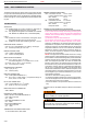
THERMOCOUPLE CIRCUIT
Total resistance of thermocouple circuit should be minimized to
ensure proper operation.
Figure 10 Figure 11 Figure 12
NOTICE
The use of the Mertik Maxitrol interrupter block is recommended.
Keep connection of interrupter block and thermocouple clean
and dry. Avoid excessive bending of the thermocouple tubing dur-
ing installation (min. 1ʺ radius; 2.5 cm) as this can cause it to fail.
1. Tighten brass interrupter block into valve ¼ turn beyond nger
tight. If necessary, an additional ¼ turn is possible.