
Users Manual Part 1


8 / 30
INSTALLATION AND OPERATING INSTRUCTIONS DRAFT FOR OEM USE ONLY
© 2019 Mertik Maxitrol GmbH & Co. KG, All Rights Reserved.
Vented Gas Appliances
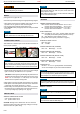
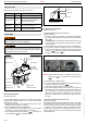
⅜ to ½ in.
(10 to13 mm)
Thermocouple
Figure 15: Proper Flame Impingement on Thermocouple
Outlet Pressure Adjustment
(Vented Units Only)
STANDARD REGULATOR OR THROTTLE
(Throttle CE Only)
1. Connect a pressure manometer to the valve outlet pressure
tap. Pressure tap is opened by turning the screw counterclock-
wise
.
Pressure regulator or throttle are located under the cover and
can be reached by removing the plug (see gures 14, page 8
and 16, page 8).
2. Turn MANUAL knob and main valve knob to the ON position.
3. Turn pressure regulator adjustment screw to set required
burner pressure (high re). Pressure is increased by turning
clockwise
(pressure regulator models), or decreased by
turning counterclockwise
.
Pressure Regulator or Throttle
Figure 16: Combination Control GV60, Cover
NOTE: Throttle model’s pressure is increased by turning coun-
terclockwise
; or decreased by turning clockwise
.
4. After adjustment, replace the plug.
5. If no other adjustments are required, close pressure tap(s) by
turning the screw(s) full clockwise
.
Check all connections / pressure tap(s) for leaks.
6. If the desired outlet pressure or ow cannot be achieved by
adjusting the gas valve, check the gas valve inlet pressure us-
ing a manometer at the valve inlet pressure tap. If the inlet
pressure is in the normal range, replace the gas valve; other-
wise, take necessary steps to assure proper gas pressure to
the valve.
CONVERTIBLE PRESSURE REGULATOR
(CSA Only; Optional)
Convertible regulators are designed to deliver either of two xed
outlet pressures for Natural Gas (NG) or LP Gas. To change
from one gas to the other, turn the conversion plug (see gure
17, page 9) counter clockwise to remove. Unsnap and remove
the plastic part, rotate it 180°, and then slide it back on the con-
version plug until it snaps. Turn the conversion plug clockwise
until it bottoms out.
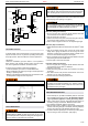
KNOB SETTINGS
Knobs function as follows (see gure 14, page 8):
KNOB POSITION FUNCTION
Main valve knob OFF Prevents main gas ow through valve.
Main valve knob ON
Permits main gas ow through valve
if the pilot is lit and thermocouple is
generating sufcient power.
Manual knob MAN
Allows the pilot to be manually ignited
and prevents main gas ow.
Manual knob ON Allows for automatic ignition.
ADJUSTMENT
It is the appliance manufacturerʼs responsibility to determine
GV60ʼs suitability for a specific application.
Do not attempt to remove screws from the top of gas valve.
Do not change any adjustments marked with tamper indicating
paint. Motor knob is not to be removed.
Side Outlet
Side Inlet
Main Valve Knob
Manual Knob
Bottom
Outlet
Bottom
Inlet
Pressure Regulator
(remove plug rst)
Inlet Pressure Tap
Outlet Pressure Tap
Pilot Gas Adjustment
Screw (turn with screw-
driver)
Magnet Unit
Minimum Rate Orice
Connection
Piezo Igniter
Tab 2.8 x 0.8 mm
Figure 14: GV60, Connections and Adjustment Options
Pilot Flame Adjustment
(Vented Units Only)
The pilot ow adjustment is preset to maximum at the factory.
The pilot ame should envelope ⅜ʺ to ½ʺ of the thermocouple
(see gure 15, page 8).
1. The adjustment screw can be reached through a hole in the
MANUAL knob (see gure 14, page 8).
2. Turn the MANUAL knob to the ON position.
3. It is now possible to pierce through a lm on the cover with a
screwdriver to reach the adjustment screw beneath.
4. Turn the adjustment screw clockwise
to decrease or
counterclockwise
to increase pilot ame.