
Users Manual Part 1


7 / 30
ENGLISH
INSTALLATION AND OPERATING INSTRUCTIONS DR AFT FOR OEM USE ONLY
© 2019 Mertik Maxitrol GmbH & Co. KG, All Rights Reserved.
To avoid damaging the electronics, do NOT use metal tools to
remove the batteries from the handset / receiver.
▪ Without using a mains adapter, battery replacement is recom-
mended at the beginning of each heating season.
▪ Old or dead batteries should be removed immediately. If left
in the unit the batteries can overheat, leak, and / or explode.
▪ Do NOT expose batteries (including during storage) to direct
sunlight, excessive heat, re, moisture, or severe impact. Each
of these conditions can cause the batteries to overheat, leak,
and / or explode.
▪ Batteries must be kept within their recommended temperature
limits (ambient battery temperature range: 32 °F to 131 °F /
0 °C to 55 °C).
▪ New and old batteries and different brands of batteries should
not be used together. Mixing of various batteries can cause
the batteries to overheat, leak, and / or explode.
▪ Low battery indication: frequent beeps for 3 seconds when mo-
tor turns.
▪ The V module for fan speed control and light / dimmer provides
the receiver with power. The batteries in the receiver can be
used for automatic backup in case of power outage.
NOTICE
To keep the receiver free from debris, dirt, and humidity, do not
remove the receiver from the plastic bag until all construction
is complete.
Radio Frequency Receiver and Handset
A code is selected automatically for all Mertik Maxitrol electronics
from among 65,000 codes available. The receiver must be paired
with a handset.
Synchronization Receiver / Symax Handset
(First time use only)
1. Insert batteries or connect AC mains power. The module for
circulating fan and light / dimmer includes a mains adapter.
With mains adapter, batteries can be used for backup.
2. Place ON / OFF switch (if equipped) to ON position.
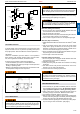
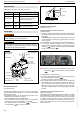
3. The receiver has to learn the Symax code:
Press and hold the receiver’s reset button (see gure 28, page
26) until you hear two (2) beeps. After the second, longer beep,
release the reset button. Within the subsequent 20 seconds
press the
button on the Symax. "CONN" and a running num-
ber from 1 to 8 are displayed on the Symax confirming the
synchronization and data exchange is in process (see gure
13, page 7). Two (2) short beeps conrm the code is set. After
successful synchronization the current state of the gas re is
displayed on the Symax.
Figure 13: Synchronization of Symax handset in process
NOTE: This is a one time setting only, and it is not required
after changing the batteries in the Symax or receiver.
NOTE: Both the receiver and the Symax transmit and receive
signals (bidirectional). The Symax and receiver sync
status information every 10 s during the rst 2 min and
afterward every 4 to 6 min.
NOTE: When the RF receiver is placed in the appliance, the
surrounding metal can reduce reception considerably.
NOTICE
The handsets and receivers are not interchangeable with previ-
ous electronics G6R and B6R-R8(9)U(T).
Synchronization Receiver / The Puck Handset
(First time use only)
1. Insert batteries or connect AC mains power. The module for
circulating fan and light / dimmer includes a mains adapter.
With mains adapter, batteries can be used for backup.
2. Place ON / OFF switch (if equipped) to ON position.
3. The receiver has to learn the Puck's code:
Press and hold the receiver’s reset button (see gure 28, page
26) until you hear two (2) beeps. After the second, longer beep,
release the reset button. Within the subsequent 20 seconds
press and hold the "–" button on the Puck (approx. 4 seconds)
until two (2) short beeps conrm the code is set.
NOTE: This is a one time setting only, and it is not required
after changing the batteries in the Puck or receiver.
NOTE: The receiver transmits and receives (bidirectional) sig-
nals and the Puck (unidirectional) transmits signals.
The Puck sends status information every 4 to 6 min to
the receiver.
NOTE: When the RF receiver is placed in the appliance, the
surrounding metal can reduce reception considerably.
NOTICE
The handsets and receivers are not interchangeable with previ-
ous electronics G6R and B6R-R8(9)U(T).
V MODULE
POWER SUPPLY
CSA: Inlet: 115 VAC / 60 Hz; 210 VA
Outlet: 115 VAC / 60 Hz; 100 VA each
Built-in fuse: 2.5 A
CE: Inlet: 230 VAC / 50 Hz; 210 VA
Outlet: 230 VAC / 50 Hz; 100 VA each
Built-in fuse: 2.5 A
AMBIENT TEMPERATURE RANGE
CSA: V Module: 176 °F
CE: V Module: 80 °C
POWER CONSUMPTION (STANDBY)
CSA + CE: G6R-B...V3: 0.3 W
POWER CONSUMPTION (NOMINAL)
CSA + CE: Depends on connected devices (fan, light)
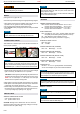
Follow wiring diagram (see gure 31, page 29). Connect the Fan
and Light rst and then connect the power supply. An LED indi-
cates the power is ON. Use Molex connectors or connect wires
to screw terminals.