Meru OAP180 Rugged Access Point Special Release Notes Beta Release 3.4-SR2 Copyright © Meru Networks, Inc., 2003–2007. All rights reserved. Other names and brands may be claimed as the property of others. Document Number: 3.4-SR2 Rev.
Contents z Introduction z OAP180 Access Point Features z OAP180 Hardware Installation Instructions z Limitations and Advisories z Documentation for this Release z Contacting Meru Introduction This special release note introduces the Meru OAP180 Access Point, a new outdoor addition to the Meru Wireless LAN (WLAN) System. Read this note before installing or using the OAP180 Access Point and the corresponding System Director version 3.4-SR2. The release notes for System Director release 3.
Designed for Harsh Conditions The OAP180 Access Point with dual-radio is designed to provide secure Wi-Fi connectivity to outdoor locations such as campuses, parking lots, and pole tops, or to harsh indoor locations such as breweries, food processing plants or warehouses. The OAP180 includes basic Voice over WLAN (VoWLAN) support.
Multiple Antennas Supported for Specific Needs WLAN Client Support The following WLAN clients are supported: z Dual 802.11a and 802.11b/g radios z Simultaneous support for 802.11a, 802.11b, and 802.
ip ftp|sftp|scp|tftp username and ip ftp|sftp|scp password commands. (Using these commands is optional. If you do not set the username and password before transferring files, you must provide the username and password when prompted.) mc500# configure terminal mc500(config)# ip ftp username user1 mc500(config)# ip ftp password userpass mc500(config)# ^Z mc500# dir ftp://myserver/images/ total 134576 -rw-rw-r-1 root root 21790720 Jul 14 17:03 meru-3.2SR2-9MC500.
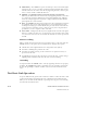
Unpack the OAP180 Confirm that the OAP180 shipping box contains the following items: z Meru Networks Meru OAP180 Outdoor Access Point (see Figure 1). Figure 1: OAP180 z Wall/Pole Mount Hardware Kit for mounting OAP180 to a 1.
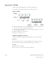
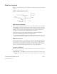
Plan the Location When you plan the OAP180 physical configuration, include the elements shown in this drawing: Figure 2: Sample Physical Layout Radio Position Planning Never construct a radio mast, pole, or tower near overhead power lines. In addition, local regulations may limit or prevent construction of a high radio mast or tower. If your OAP180 link requires a high radio mast or tower, consult a professional contractor for advice.
z Wind Velocity — The OAP180 can operate in winds up to 44 m/s and survive higher wind speeds up to 66 m/s. You must consider the known maximum wind velocity and direction at the site and be sure that any supporting structure, such as a pole, mast, or tower, is built to withstand this force. z Lightning — The OAP180 includes its own built-in lightning surge protection. However, you should make sure that the unit, any supporting structure, and cables are all properly grounded.
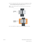
Mount the Unit The OAP180 can be mounted on the following two surfaces (brackets are included): z 1.5 to 2 inch diameter pole z Wall Mounting OAP180 with the Pole-Mounting Bracket Perform the following steps to mount the unit to a 1.5 to 2 inch diameter steel pole or tube using the mounting bracket: 1. Attach the OAP180 to the mounting bracket shown in Figure 3. Figure 3: Square Mounting Bracket Attaches to Bottom of OAP180 OAP180 Hardware Installation Instructions © 2007 Meru Networks, Inc.
2. Place the V-shaped part of the bracket around the pole and tighten the securing nuts just enough to hold the bracket to the pole. (The bracket may need to be rotated around the pole during the alignment process.) Always attach the bracket to a pole with the open end of the mounting grooves facing up. Note: 3. Use the included nuts to tightly secure the wireless OAP180 to the bracket. 10 of 24 OAP180 Hardware Installation Instructions © 2007 Meru Networks, Inc.
4. Connect the OAP180 bracket and the pole bracket. See Figure 4. Figure 4: Connecting the Two Brackets Mounting OAP180 with the Wall-Mounting Bracket Attach the bracket to a wall with the flat side flush against the wall (see Figure 5). Perform the following steps to mount the unit to a wall using the wall-mounting bracket: 1. Position the bracket in the intended location and mark the position of the four mounting screw holes. 2.
4. Connect the two brackets as shown in Figure 6. Figure 6: Connecting the Two Brackets 12 of 24 OAP180 Hardware Installation Instructions © 2007 Meru Networks, Inc.
Connect External Antennas and Ground Wire to OAP180 When deploying an OAP180, first mount external antennas and then connect them to the OAP180. Follow these steps: 1. Mount the external antenna on the same supporting structure as you did the OAP180, within 3 m (10 ft) of it, using the bracket supplied in the antenna package. 2. Connect the antenna to the OAP180’s N-type connector using the RF coaxial cable provided in the antenna package. Figure 7: Connect the Antenna Cables 3.
Connect Cables to the Unit Use only the provided Ethernet cable in step 1. Do not shorten this cable as the path loss is needed. During periods of lightning activity, do not connect or disconnect cables or otherwise work with the OAP180. Perform the following steps to attach the Ethernet cable and ground wire: 1. Using the included cable, attach the Ethernet cable to the Ethernet port on the OAP180. See Figure 8. Figure 8: Connecting the Ethernet Cable and Ground Wire 2.
Connect the Power Injector Caution! Do not locate the power injector outdoors. The unit is for indoor use only. Note: The wireless Ethernet port does not support Power over Ethernet (PoE) based on the IEEE 802.3af standard. Do not try to power the unit by connecting it directly to a network switch that provides IEEE 802.3af PoE. Always connect the unit to the included power injector module. Perform the following steps to connect the power injector: 1.
Align Antenna After the OAP180 unit is mounted, connected, and the radios are operating, the antennas must be accurately aligned to ensure optimum performance of the OAP180 links. In this point-to-multipoint configuration all OAP180 nodes must be aligned with the root OAP180 antenna. Check the OAP180 for Activity Check the OAP180 LEDs for activity. Four of the eight LEDs on the bottom of the OAP180 indicate activity; four LEDs are not used at this time.
Configure the OAP180 Access Point Once the OAP180 is plugged in, the Meru controller will detect and connect the OAP180. The OAP180 can then be further configured through either the Controller GUI or CLI. Configure OAP180 Radio Operation with the Web UI Configure OAP180 Radio Antennas with the CLI Configure OAP180 Radio Operation with the CLI Configure OAP180 Radio Operation with the Web UI To use the Web UI to set up the OAP180, follow these steps from the controller: 1.
Configure OAP180 Radio Operation with the CLI To configure radio parameters of OAP180 through the IOSCLI, follow these steps from controller. This example uses AP ID 1 and interface IDs 1 and 2: 1. First, configure AP ID 1 and Interface ID 1 (B/G Interface): MC3000# configure terminal MC3000(config)# interface Dot11Radio 1 1 MC3000(config-if-802)# channel 1 MC3000(config-if-802)# rf-mode 802.11g MC3000(config-if-802)# exit MC3000(config)# 2.
MC3000# show interfaces Dot11Radio 1 2 Wireless Interface Configuration AP ID AP Name Interface Index AP Model Description Administrative Status Operational Status Last Change Time Radio Type MTU (bytes) Channel Short Preamble RF Band Support RF Band Selection Antenna Selection Transmit Power (dBm) (low,medium,high) AP Mode Fixed Channel Scanning Channels Protection Mechanism Protection Mode OAP180 Hardware Installation Instructions © 2007 Meru Networks, Inc.
Configure OAP180 Radio Antennas with the CLI Configure OAP180 antennas with the following CLI commands. This example uses AP ID 10 and radios 1 and 2: 1. Enter the Radio sub-mode from global configuration, by specifying the AP ID (10 in the example) and first interface that you intend to configure: default# configure terminal default(config)# interface Dot11Radio 10 1 2. Enter the antenna-property submode interface 1: default(config-if-802)# antenna-property 1 3.
Limitations and Advisories Known Bugs for this Release ! BUG ID Summary Other Significant Issues with this Release None Regulatory Information Radio z FCC Part 15 z Canada RSS210 z EN 300 328 V1.6.1 (11/2004) z EN 301 893 V1.3.1 (08/2005) z Japan Technical Regulations EMC z FCC Part 15 z EN 301 489-17 V1.2.1 (08/2002) z Japan VCCI Limitations and Advisories © 2007 Meru Networks, Inc.
Safety z cUL 60950-1 First Edition z IEC/EN 60950-1 First Edition z with national deviations z UL 50; Enclosures for Electrical Equipment FCC Statement This equipment has been tested and found to comply with the limits for a Class B digital device, pursuant to Part 15 of the FCC Rules. These limits are designed to provide reasonable protection against harmful interference in a residential installation.
For product available in the USA market, only channel 1~11 can be operated. Selection of other channels is not possible. FCC NOTICE To comply with FCC part 15 rules in the United States, the system must be professionally installed to ensure compliance with the Part FCC 15 certification It is the responsibility of the operator and professional installer to ensure that only certified systems are deployed in the United States.
Contacting Meru You can visit Meru Networks on the Internet at this URL: http://www.merunetworks.com Click Support to view Meru Customer Services and Support information. Customer Services and Support For assistance, contact Meru Customer Services and Support 24 hours a day at 1-888637-8952 (1-888-Meru-WLA(N)) or 1-408-215-5305. Send email to support@merunetworks.com.