www.messoa.
Cautions The camera must be installed on a solid mounting surface. Please make sure the power source is AC 24V / PoE+. Although the camera can be powered via a PoE+ connection, the PoE+ power source won’t be able to drive the camera with its equipped heater being operating simultaneously. Users are supposed only to supply the camera with AC 24V continuously for the heater inside the camera to operate. Keep the camera and other accessories dry.
FCC Class A Compliance Statement This device complies with Part 15 of the FCC Rules. Operation is subject to the following two conditions: (1) this device may not cause harmful interference, and (2) this device must accept any interference received, including interference that may cause undesired operation. Any changes or modifications to the equipment not expressly approved by MESSOA could void the user’s authority to operate the equipment.
Table of Contents Table of Contents 1. Overview.................................................................................................................................... 5 1.1 Introduction.......................................................................................................................................5 1.2 Package Contents..............................................................................................................................5 1.3 Dimensions..............
Table of Contents 3.5 System..............................................................................................................................................45 3.5.1 Password................................................................................................................................................ 45 3.5.2 Date/Time.............................................................................................................................................. 46 3.5.3 Firmware.
1. Overview 1. Overview 1.1 Introduction The NIC990 is designed to provide crystal-clear 16:9 full HD video for outdoor applications in both day and night. With the support of H.264 compression, NIC990 offers you high quality images yet without the need of high bandwidth and storage capacity. It also features superior WDR, white balance and AE controls to handle the variations of luminance and thus ensures you don’t miss a thing.
1. Overview 1.3 Dimensions H Ø Unit (Ø x H): 216.14mm X 360.19mm (8.51" X 14.
1. Overview 1.
1.
1. Overview 1.5 Specifications Frequency Control Motion Detection Video Sensor Type 1/2.8" image sensor(CMOS) Others Active Pixels 1920x1080 (HxV) Events Compression H.264 / MJPEG Streaming Dual streaming Resolution 1080P, 720P, 480P, VGA, QVGA, CIF Max. Frame Rate Day/Night Day/Night Mode Shutter Time 2MP 16:9 (1920x1080) at 30 fps (NTSC/ PAL) Mechanical (ICR) D/N control Auto, Day, Night 1/10000s to 1s selectable (60Hz/50Hz) Minimum Illumination Color 0.4 Lux, B/W 0.
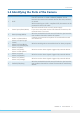
2. Getting Started 2. Getting Started This chapter is intended to give information and instructions for installing and conducting the initial configuration of the network camera. Sections within this chapter include mounting, power wiring, network deployment, IP Finder utility installation and how to use IP Finder. 2.1 Installing the Camera 2.1.1 Mounting the IP Camera The camera supports several mounting methods.
2. Getting Started 2.1.2 Connecting to a Power Supply The camera does not include an On/Off switch. The equipment is simply connected to/ disconnect from a power source to power on/off. Users can power the equipment on by one of the following options: Caution Tip • 24 VAC: Connect the power input terminal block of the equipment to a 24VAC power source. • POE+: Connect the equipment via a category 5/5e or higer UTP/STP cable to a POE+ (802.3at) compliant router or Ethernet switch.
2. Getting Started Caution Tip Note Although an RJ-45 coupler is used to extend the connection length, the total length between the PC and the IP camera must not be longer than 100 meters (328 feet). The LAN port of the camera supports auto MDI/MDIX (Medium dependent interface crossover) so there is no need to use crossover cable. To access the camera, the PC must be on the same network segment as the camera. The default IP address of the camera is a static one (192.168.1.30).
2. Getting Started Router xDSL/Cable Modem To access the camera from a local PC, simply use the local IP address of the camera. To enable remote access, you must configure your router/firewall to forward an incoming request to that fixed local IP address of the camera. Therefore, when an external host sends a request to access your camera, the request will first reach the router’s external IP address and then be forwarded to the local IP address of the camera. 2.
2. Getting Started Step 2: IP Address Configuration for PC The camera uses a default IP address of 192.168.1.30 and subnet mask of 255.255.255.0. To have your PC on the same network segment with the camera, configure your PC’s IP settings as below: IP address: 192.168.1.X (where X is a number between 2 to 254, excluding 30). Subnet mask: 255.255.255.0. Ignore all other settings and click OK. Step 3: Link Verification between PC and Camera 1.
2. Getting Started When prompted for login, enter the user name and the password respectively (The defaults: admin, 1234). Note that the user name and password are case-sensitive.
2. Getting Started 2.3 Using “IP Finder” to Manage Cameras IP Finder is a management tool included on the product CD. It is designed to manage your network cameras on the LAN. It can help find multiple network cameras, set IP addresses, and show connection status. 2.3.1 Installing IP Finder Before proceeding, make sure your operating system is Windows 7, Windows Vista or Windows XP. To install the software, simply locate and double-click the IP Finder setup file on the provided CD.
2. Getting Started Search Network: This option allows you to search the cameras on the network. Set Master ID and Password: Allows you to set a master ID and password for managing the cameras with IP Finder. Management Tool: Allows you to restart the camera and reset all of the camera settings to default (except network settings). Caution Tip Note The management tool does’t support Update Firmware and Hard Factory Default functions for NIC990.
2.
3. Web-based Interface 3. Web-based Interface 3.1 Live View Images of the network camera can be viewed through the web browser of your personal computer. If the camera image screen is not displayed, check your browser settings. Preparations before Displaying Enable cookies. Change Security in Internet options as follows: 1. Click Internet Options on the Tools menu. 2. Click the Security tab. 3.
3. Web-based Interface 5. A Local Area Network (LAN) Settings dialog window shows up. 6. Check if the checkbox Will use a proxy server is ticked. If the checkbox is not ticked, the browser is not set to use a proxy server. Click Cancel and quit setting. If the checkbox is ticked, click Detail setting. A proxy setup screen will appear. 7. Enter the IP addresses of the network cameras in the field marked Do not use the proxy server with addresses started with the following. 8. Click OK.
3. Web-based Interface 3.1.1 Using the Live Player - Web Images of the network camera can be viewed through the web browser of your personal computer. Click the Live hyperlink to display live view which is being monitored by the camera. If the camera image screen is not displayed, check your browser settings. And then click the PTZ icon to bring the control panle window. The table below gives brief descriptions for the control panel to adjust the camera. 1.
3. Web-based Interface 3.2 Information Click the Setup hyperlink at the top right-hand corner entering the web interface to configure the IP camera. When you enter the setup interface, the Information page shows up first displaying hardware version, MAC address and MCU version. 3.3 Image 3.3.1 Basic Settings Click Basic Settings on the left-hand menu. Then the screen of Camera - Basic Settings will appear. Image Color Auto Exposure: Auto Exposure controls the light intensity of picture.
3. Web-based Interface camera depending on your application environment. When Full Automatic is selected, the EV item is then available. EV: EV is called exposure compensation that tells the camera for a particular scene you want it either brighter (zero to +7) or darker (zero to -7). The EV value from -7 to 7 is only available in Full Automatic mode. Exposure Time: Exposure Time between 1 and 1/10000 seconds is only available in Shutter Priority mode.
3. Web-based Interface visible while retaining details in bright areas. Users can set it at OFF, ON, Exposure, Histogram or Auto. • OFF/ON: Click the drop-down menu to disable/enable WDR. • Exposure: Set when the camera is located in a field where light is strong. • Histogram: Set for indoor environments. • Auto: With Auto selected, the camera will choose ON or OFF automatically according to surrounding environment. Note that when set at ON, the frame rate is half decreased.
3. Web-based Interface Pan/Tilt Auto Flip: Click the radio buttons to select ON or OFF. The Auto Flip feature allows the camera to tilt 180 degrees and to relocate itself for continuous viewing of a moving object directly beneath the camera. Proportional P/T: Set at ON or OFF. Proportional P/T controls the pan and tilt speeds according to the zoom factor. In tele mode, the pan and tilt speeds will be reduced for a better usage.
3. Web-based Interface 3.3.2 Auto Patrol Patrol Settings: This interface allows users to configure up to four groups of patrolling presets for auto patrol function. Patrol: Select among the four preset groups by clicking the drop-down menu. Stop time: Determine stop time among 3, 5, 7, 15, 30 and 60s for auto/ frame /random scan.
3. Web-based Interface When finishing configurations, remember to click the Save button to have the configurations take effect. 3.3.3 Privacy Zone Users can define up to eight privacy zone by dragging the mouse to form a rectangular mask on the monitored view to protect necessary privacy. The size and position of these framed areas can be adjusted according to the horizontal pan, vertical tilt, and lens zoom of the camera. 1.
3. Web-based Interface Caution Tip Note It is recommended to set the privacy zone slightly larger than the actual area to ensure that privacy area is not revealed during movement. Privacy zone will zoom in/out in accordance with the lens zoom level to ensure the effect. 3.3.4 Codec 1. Click Codec on the left-hand menu to display the Codec Settings interface. 2. Configure the options described in the table below.
3. Web-based Interface 3. Click Save. Video Codec mode Resolution Bit Rate Rate Control GOP Image Quality Multicast Address Transfer Type RTSP Port Number Video Port Number Caution Tip H.264 MJPEG Higher resolution results in larger image sizes.
3. Web-based Interface Alarm Input 1. Click the ON radio button to enable the six Alarm In functions. 2. Input Type: Set the alarm contact type on Normal Open or Normal Close. For alarm input type, the active state is always Normal Open. 3. Action: Specify the action to be taken when an alarm is triggered. No action will be taken if the drop-down menu is set at OFF. Caution Tip Note The Input Type and Action settings are available when the particular alarm-in function is not set at ON.
3. Web-based Interface Alarm Output Click the drop-down menu to set Alarm Mode at OFF, Event or Extra. When the mode is set at OFF, this function is disabled. With Event selected, if any one of the alarm inputs is triggered, the camera will send a warning through the alarm output. Also users are supposed to set Delay Time on 1, 5, 10, 15, 30 or 60 seconds for relaying the alarm. As for Extra, this option is for advanced users to enter cgi commands in the URL of the web browser.
3. Web-based Interface When you click SD Card Recording on the left-hand menu, a message dialog box will pop up if the stream mode is set on H264 (1080p). To start configuring SD Card recording users are supposed to set stream mode on options other than H264 (1080p). Please refer to the Codec section for further details. Recording Settings Trigger Mode: Configure the triger modes to store image files according to the scheduled recording plan or the moment an event occurs.
3. Web-based Interface Period Settings This interface shows up beneath the Recording Settings only when the Scheduled Recording radio button is selected. Recording Schedule: Determine the recording condition: OFF, All Day, Schedule 1 or Schedule 2 from the recording schedule table for all days from Monday to Sunday. Schedule 1/Schedule 2: After selecting either Schedule 1 or Schedule 2 radio button, users are supposed to specify the start/stop time by clicking the drop-down menus respectively.
3. Web-based Interface Overwrite Click ON to enable overwriteing if the SD card has used up its storage capacity. With OFF selected, the system will stop writing to the SD card. Click Save to have the configuration take effect. Recording Files Click Delete All to empty the SD card. Click Delete Event Recording Files to delete all files stored by event recording. Click Delete Schedule Recording Files to delete all files stored by scheduled recording.
3. Web-based Interface 3.3.7 FTP Recording You can save image files via FTP. Configure your FTP recording condition first, and then identify your FTP sever 1 and 2. When you click FTP Recording on the left-hand menu, a message dialog box will pop up if the stream mode is set on H264 (1080p). To start configuring FTP recording users are supposed to set stream mode on options other than H264 (1080p). Please refer to the Codec section for further details.
3. Web-based Interface Recording Settings Trigger Mode You can store your image files based on your scheduled recording, recording by alarm or recording by motion detection.
3. Web-based Interface Scheduled Recording: By clicking the Scheduled Recording radio button, the Schedule Settings interface which needs to be configured as a scheduled recording plan will then be shown at the bottom of the screen. Event Recording: By clicking this radio button, the Event Recording Settings will then be shown at the bottom of the screen. • Alarm In: This check box is available only when any of the six Alarm In items is set at ON (see the External Alarms section).
3. Web-based Interface Event Recording Settings This interface shows up at the bottom of this page only when the Event Recording radio button is selected. The scheduled recording is triggered by alarm-in or motion detection according to the check boxes in the Recording Settings you have ticked. Please finish the configurations as follows. Pre-Recording: Set the number of images to be recorded before an event (alarm or motion detection) occurs. Images of the moment when an event occurs are not included.
3. Web-based Interface • Reconnect: The network camera logs in/out for each file transfer. • Continuous Connection: The network camera is always in connection. FTP Server Usage You can choose to save your image files to either FTP server 1, 2, or automatically switching servers. Primary Server: Define FTP server 1 or 2 as the primary server for saving image files.
3. Web-based Interface • PLAIN: PLAIN is the name of a registered SASL authentication mechanism, which is supplied as a parameter to the AUTH command. The PLAIN authentication mechanism is described in RFC 2595. PLAIN is the least secure of all the SASL authentication mechanisms, since the password is sent unencrypted across the network. • LOGIN: The LOGIN mechanism is supported by Microsoft’s Outlook Express, as well as by some other clients.
3. Web-based Interface E-mail Address List Click the ‘ON’ radio button to enable sending E-mail to the administrator when events occur. Besides, you can also assign a list of recipients to receive E-mail triggered by alarm-in or motion detection event.
3. Web-based Interface 3.3.9 Audio Specify the audio codec method and audio input level. Format Click the drop-down menu to select audio codec formats of PCM, G711-Alaw and G711-Ulaw. Audio In Function: Set at ON to receive audio from a microphone connected to the camera. Audio Input Level: Low / Mid / High selectable. 3.4 Network 3.4.1 Basic Network Settings Camera Name: Enter your camera name or use the default name.
3. Web-based Interface HTTP Port: We recommend using the default port (80). If you need to change the port number, please contact your system administrator. The port number should be in the range between 1025 and 65535. Host Name: Specify the host name. Domain Name: Specify the domain name. UPnP Use UPnP: When ON is selected, the camera can be detected automatically by the PC. Therefore, it is not necessary to install the IP Camera Finder program.
3. Web-based Interface DDNS: Click ‘ON’ to activate the DDNS function or ‘OFF’ to disable the DDNS function. DDNS Server: Click the drop-down menu to select a DDNS server including DynDNS, DHS and NoIP. User ID: Fill in the field with a user’s ID. Password: Enter a password associated with the user ID. Password (Confirm): Re-enter a password to confirm it. Finally, click Save to save the settings. 3.4.
3. Web-based Interface When finished, click the Save button to have the configuration take effect. 3.5 System 3.5.1 Password Administrator Setup Click Password on the left-hand menu to display the Administrator Setup interface. The default values for system Admin ID and password are: • Admin. ID: admin • Password: 1234 Here you can change your own Admin ID and password. Aftert setting is done, click Save to have the configurations take effect.
3. Web-based Interface User 1 ~ 5 Setup Besides the administrator role, users with the guest authority from system administrator can also access the camera. However, Users 1 ~ 5 are allowed only to review the live picture. Without authorization, any operation will be forbidden. Both the default guest’s login name and password are ‘guest’. User ID: Fill a guest’s User ID in the User ID field. Password: Fill in a password associated with a guest’s User ID.
3. Web-based Interface Sync with NTP Server When this function is enabled, the Setup Manually interface is then unavailable. Select ON to enable the NTP Server function. When enabled, the date and time will be synchronized by the NTP server on the Internet. You can also set the time period for NTP time synchronizing. The button Save & Test can test the NTP Server Time.
3. Web-based Interface 3.5.4 Configuraion Import Settings This function is designed to upload configuration from the client computer to network cameras. 1. Click the Browse button to locate the files on the client computer. 2. Make sure the file located is the correct one for upload. 3. Click the Import button to start the upload process. Export Settings This function is designed to download configuration from this network camera to the client computer.
3. Web-based Interface Set to Factory Default This function is designed to reset all configurations into factory default. Just click the Deafult button and then a dialog box shows up to ask you to restart the camera. Reboot This function is designed to reboot the camera. Clicking the Reboot button and a dialog box appears with confirmation message. Click OK to reboot the network camera. 3.6 Event Log Click Event Log on the left-hand menu to display the Event Log interface.
MESSOA TAIWAN, R.O.C. 6F, No.26, Wuquan 6th Rd., Wugu District, New Taipei City 248, Taiwan (R.O.C.) Tel: +886-2-2298-3908 Fax: +886-2-2298-3909 E-mail: info@messoa.com MESSOA USA 13611 12th St, Unit B Chino, CA 91710, USA Tel: +1-909-590-5955 Fax: +1-909-590-2374 E-mail: info@messoa.com MESSOA SHANGHAI INC. Room 301, Yuanzhong Office Building, No.2007 Hongmei Rd., Xuhui District, Shanghai 201103 Tel: +86-21-6495-9236 Fax: +86-21-6495-9238 E-mail: info@messoa.