
Specifications


29
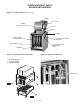
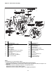
POWER VENTED BLOWER
UNIT NUMBER DESCRIPTION
Digit #1, 2 - Unit Type [UT]
B2 - Power Vented Blower
Digit #3, 4, 5 - Capacity [CA]
100 - 100,000 BTU/HR
125 - 125,000 BTU/HR
150 - 150,000 BTU/HR
175 - 175,000 BTU/HR
200 - 200,000 BTU/HR
250 - 250,000 BTU/HR
300 - 300,000 BTU/HR
350 - 350,000 BTU/HR
400 - 400,000 BTU/HR
Digit #6 - Furnace Type [FT]
A - Right Side Access
Digit #7 - Heat Exchanger Construction Material [FM]
1 - Aluminized Steel
2 - 409 Stainless Steel
3 - 321 Stainless Steel
Digit #8 - Gas Type [GT]
N - Natural Gas
P - Propane Gas (LP)
K - Natural Gas w/100% Shutoff
Digit #9 - Ignition Control [IC]
2 - Spark Ignition
Digit #10 - Altitude [AL]
A - 0–1,999 ft. J - 8,000–8,999 ft.
B - 2,000–2,999 ft. K - 9,000–9,999 ft.
C - 3,000–3,999 ft. L - 10,000–10,999 ft.
D - 4,000–4,999 ft. M - 11,000–11,999 ft.
F - 5,000–5,999 ft. N - Local Gas Supplier Derate
G - 6,000–6,999 ft. P - Canadian High Altitude 2,000–4,500 ft.
H - 7,000–7,999 ft.
Digit #11 - Gas Control [GC]
A - Single Stage
B - Two Stage
H - Electronic Modulation w/Room Sensing
J - Electronic Modulation w/Duct Sensing
K - Electronic Modulation w/Duct Sensing & Room Override Stat
L - Electronic Modulation w/External 4-20 mA Input
N - Electronic Modulation w/External 0-10 VDC Input
Digit #12 - Supply Voltage [SV]
1 - 115/1/60 5 - 230/3/60
2 - 208/1/60 6 - 460/3/60
3 - 230/1/60 7 - 575/3/60
4 - 208/3/60 Z - Special
Note: Supply Voltages [SV] 2-7 include fi eld mounted step down transformer.
Digit #13 - Motor Type [MT]
1 - Open Drip Proof
2 - Totally Enclosed
3 - Premium Effi ciency, Open Drip Proof
4 - Premium Effi ciency, Totally Enclosed
Digit #14 - Blower Motor Sizes [MS]*
A - 1/4 HP w/Contactor M - 3/4 HP
B - 1/3 HP w/Contactor N - 1 HP
C - 1/2 HP w/Contactor P - 1/2 HP w/Magnetic Starter
D - 3/4 HP w/Contactor R - 3/4 HP w/Magnetic Starter
F - 1 HP w/Contactor S - 1 HP w/Magnetic Starter
G - 1-1/2 HP w/Contactor T - 1-1/2 HP w/Magnetic Starter
H - 2 HP w/Contactor U - 2 HP w/Magnetic Starter
J - 1/4 HP W - 1/4 HP w/Magnetic Starter
K - 1/3 HP Y - 1/3 HP w/Magnetic Starter
L - 1/2 HP
*Notes: 1. All 3-phase units [SV = 4, 5, 6, 7] include a contactor as standard.
2. All single phase units [SV = 1, 2, 3] include a contactor for units equipped with
1-1/2 HP. motor or higher [MS = G, H]
3.
[MS] options J, K, L, M, N only available with single phase supply voltage [SV = 1, 2, 3].
Digit #15 - Accessories [AS]
FACTORY INSTALLED
A8 - Input Derate S1 - 409 Stainless Steel Burners
S3 - 409 Stainless Steel Flue Collector
M8 - Discharge Duct Flange
P4 - Terminal Block Wiring
P6 - Summer/Winter Switch
† FIELD INSTALLED (AS-____ )
† Field Installed Accessories are not included in the Unit Number. All Field Installed
Accessories are entered as a separate line item using the catalog number which utilizes
“AS” as a prefi x. i.e: A7 becomes AS-A7.
A7 - Pressure Regulator 1/2-2 psi H5 - Low Ambient Control
F1 - 1-Stage T675A Ductstat M2-1 - Vent Caps (4") (Unit Capacity 100-175)
F2 - 2-Stage T678A Ductstat M2-2 - Vent Caps (5") (Unit Capacity 200-250)
M2-3 - Vent Caps (6") (Unit Capacity 300-400)
G1 - 1-Stage T87K Mercury Free Thermostat M3-1 - Adaptors (5"- 4") (Unit Capacity 100-175)
w/Subase Kit M7 - 2 to 4 Point Suspension Kit
G2 - 1-Stage T87K Mercury Free Thermostat
w/TG511A Guard Kit P5 - 24V SPST Relay-Specify Purpose
G3 - 1-Stage T834N Mercury Free Thermostat
w/Fan Switch Q1 - “Y” Splitter Nozzle
G5 - 2-Stage TH5220D Mercury Free Q2 - 30 Degree Nozzle
Thermostat w/Subbase Q3 - 60 Degree Nozzle
G6 - Locking Thermostat Cover Q4 - 90 Degree Nozzle
G8 - 1-Stage T6169C Line Voltage Stat Q5 -
Poly Tube Adaptor (Unit Capacity 150-400)
w/Subbase Q6 - Vertical Louvers
G9 - 1-Stage T822K Mercury Free
Thermostat
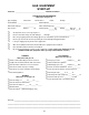
Digit X X X X — 1 2 3 4 5 6 7 8 9 10 11 12 13 14 15 +
Item
Prefi x UT CA FT FM GT IC AL GC SV MT MS AS
(Internal use Only)