GG-IOM-10 J30-08511 INSTALLATION INSTRUCTIONS AND PARTS IDENTIFICATION TUBULAR GAS FIRED DIRECT SPARK PROPELLER UNIT HEATERS – FOR COMMERCIAL, INDUSTRIAL AND RESIDENTIAL INSTALLATIONS – ATTENTION: READ THIS MANUAL AND ALL LABELS ATTACHED TO THE UNIT CAREFULLY BEFORE ATTEMPTING TO INSTALL, OPERATE OR SERVICE THESE UNITS! CHECK UNIT DATA PLATE FOR TYPE OF GAS AND ELECTRICAL SPECIFICATIONS AND MAKE CERTAIN THAT THESEAGREE WITH THOSE AT THE POINT OF INSTALLATION. RECORD THE UNIT MODEL AND SERIAL No.
TABLE OF CONTENTS SPECIFICATIONS Basic Description .................................................... 2 Performance & Specification Data ...................... 4, 5 GENERAL SAFETY INFORMATION Installation Codes ............................................... 2, 3 Special Precautions ............................................ 2, 3 INSTALLATION Locating Units ..................................................... 6, 7 Combustion Air ...................................................
GENERAL SAFETY INFORMATION Failure to comply with the general safety information may result in extensive property damage, severe personal injury, or death. Make certain that the power source conforms to the electrical requirements of the heater. Do not depend upon a thermostat or other switch as sole means of disconnecting power when installing or servicing heater. Always disconnect power at main circuit breaker as described above. Failure to do so could result in fatal electric shock.
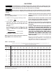
Table 1 - Performance and Dimensional Data - Tubular 30 thru 120 Propeller Unit Heater Unit Size PERFORMANCE DATA† Input - BTU/Hr. (kW) Output - BTU/Hr. (kW) Thermal Efficiency (%) Free Air Delivery - CFM (cu.
Figure 2 - Dimensional Drawing – Tubular 30 thru 120 Propeller Unit Heater D8597 DIMENSIONS .
INSTALLATION Do not install unit heaters in corrosive or flammable atmospheres! Premature failure of, or severe damage to the unit will result! AIR FOR COMBUSTION: The unit heater shall be installed in a location in which the facilities for ventilation permit satisfactory combustion of gas, proper venting, and the maintenance of ambient air at safe limits under normal conditions of use.
INSTALLATION (continued) The Unit Heater may be mounted by fastening the hanging brackets directly to ceiling joists or by suspending from four rods. See Figures 3, 4 and 5. Figure 3 - Hanger Bracket Installation Instructions Make certain that the lifting methods used to lift the heater and the method of suspension used in the field installation of the heater are capable of uniformly supporting the weight of the heater at all times.
GAS PIPING To avoid damage or possible personal injury, do not connect gas piping to this unit until a supply line pressure/leak test has been completed. Connecting the unit before completing the pressure/leak test may damage the unit gas valve and result in a fire hazard. Do not rely on a shut-off valve to isolate the unit while conducting gas pressure/leak tests. These valves may not be completely shut off, exposing the gas valve to excessive pressure and damage.
PIPE INSTALLATION 1. Install the gas piping in accordance with applicable local codes. 2. Check gas supply pressure. Each unit heater must be connected to a gas supply capable of supplying its full rated capacity as specified in Table 3. A field LP tank regulator must be used to limit the supply pressure to a maximum of 14 inches W.C. (3.5 kPa). All piping should be sized in accordance with the latest edition of ANSI Standard Z223.1 (NFPA 54) National Fuel Gas Code; in Canada, according to CSA-B149.
ELECTRICAL CONNECTIONS THERMOSTAT WIRING AND LOCATION: NOTICE: The thermostat must be mounted on a vertical, vibration-free surface, free from air currents, and in accordance with the furnished instructions. HAZARDOUS VOLTAGE! DISCONNECT ALL ELECTRIC POWER INCLUDING REMOTE DISCONNECTS BEFORE SERVICING. Failure to disconnect power before servicing can cause severe personal injury or death. Standard units are shipped for use on 115 volt, 60 hertz, single phase electric power.
ELECTRICAL CONNECTIONS (continued) Figure 10A - UT Control Board D8604 Figure 11A - Honeywell Control Board D8605 11
ELECTRICAL CONNECTIONS (continued) Figure 10B - Tubular Propeller Units 30-120 with Natural and Propane (LP) Gas with Single Stage Gas Control and UT Control Board NOTICE: See Figures 7, 8, 9, 10B, 10C, 11B and 11C for connecting the thermostat to the unit heater. If using a standard low voltage thermostat with a sub-base switch for fan control, connect the G terminal of the thermostat to the G terminal of the unit heater.
ELECTRICAL CONNECTIONS (continued) Figure 10C - Tubular Propeller Units 60-120 with Natural and Propane (LP) Gas with Optional Two Stage Gas Control and UT Control Board NOTICE: See Figures 7, 8, 9, 10B, 10C, 11B and 11C for connecting the thermostat to the unit heater. If using a standard low voltage thermostat with a sub-base switch for fan control, connect the G terminal of the thermostat to the G terminal of the unit heater.
ELECTRICAL CONNECTIONS (continued) Figure 11B - Tubular Propeller Units 30-120 with Natural and Propane (LP) Gas with Single Stage Gas Control and Honeywell Control Board NOTICE: See Figures 7, 8, 9, 10B, 10C, 11B and 11C for connecting the thermostat to the unit heater. If using a standard low voltage thermostat with a sub-base switch for fan control, connect the G terminal of the thermostat to the G terminal of the unit heater.
ELECTRICAL CONNECTIONS (continued) Figure 11C - Tubular Propeller Units 60-120 with Natural and Propane (LP) Gas with Optional Two Stage Gas Control and Honeywell Control Board NOTICE: See Figures 7, 8, 9, 10B, 10C, 11B and 11C for connecting the thermostat to the unit heater. If using a standard low voltage thermostat with a sub-base switch for fan control, connect the G terminal of the thermostat to the G terminal of the unit heater.
VENTING* All unit heaters must be vented! All Venting installations shall be in accordance with the latest edition of Part 7, Venting of Equipment of the National Fuel Gas Code, ANSI Z223.1 (NFPA 54), or applicable provisions of local building codes. All venting of residential tubular unit heaters must comply with CSA International Requirements 10.96 U.S. for Unit Heaters for Residential Use (2nd Edition). Refer to notes* below for Canadian installations. Refer to Figures 12-17.
VENTING - GENERAL GUIDELINES The following guidelines apply to all categories to follow. Table 4 Vent Systems Termination Clearance Requirements Door, window, or gravity vent inlet; combustion air inlet for other appliances USA CANADA 9 inches for 10,000 to 50,000 BTU/Hr input; 12 inches for input exceeding 50,000 BTU/Hr. 9 inches (230mm) for 10,000 to 50,000 BTU/Hr input; 12 inches (305mm) for input exceeding 50,000 BTU/Hr. Forced air inlet within 10 ft. 3 feet above 6 feet (1.
STANDARD COMBUSTION VERTICALLY VENTED, CATEGORY I - Figure 12 Observe the following precautions when venting the unit: 1. Use flue pipe of the same size as the flue connection(s) on the gas unit heater 4 inches (102mm). All heaters must be vented with a UL 1738 listed, double or single wall vent, Type B vent, a factory built chimney, or a lined brick and mor tar chimney that has been constructed in accordance with the National Building Code.
Figure 12 - Vertically Vented, Category I D9257 Figure 12A - Double Wall Draft Hood Connector D06880 19
STANDARD COMBUSTION HORIZONTALLY VENTED, CATEGORY III - Figures 13A, 14 & 16 Observe the following precautions when venting the unit: 1. Use flue pipe of the same size as the flue connection(s) on the gas unit heater, 4 inches (102mm). All heaters must be vented with a single or double wall pipe listed for category III positive pressure vent systems. (UL 1738 listed AL29-4C). 2. Each unit must have an individual vent pipe and vent terminal. Unit MUST NOT be connected to other vent systems or to a chimney.
Figure 13A - Category III Horizontal Venting Requirements Using Single Wall Vent Pipe D9259 Figure 13B - Vertically Vented, Category III D9258 21
VENTING (continued) Figure 14 D9260 Figure 15 D9261 22
VENTING (continued) Figure 16 D9262 Figure 17 D9263 23
SEPARATED COMBUSTION INSTALLATION - VENTING – CATEGORY III NOTICE: Every Separated Combustion unit to be installed MUST use the Factory available Combustion Air Inlet Kit. If you do not have this kit, contact the manufacturer ASAP to obtain one prior to installation. COMBUSTION AIR 7. The equivalent length of the combustion air system must not be less than 5 feet (1.5m) and must not exceed 30 feet (9m). Equivalent length equals the total length of straight pipe plus 5 feet (1.5m) for each 90° elbow and 2.
SEPARATED COMBUSTION VENTING (continued) 4. Use UL 1738 listed single wall pipe for the vent system. For installations in Canada, use corrosion resistant and gas-tight, listed vent pipe conforming with local building codes, or in the absence of local building codes, with current CSA-B149.1, Installation Codes for Natural Gas Burning Appliances and Equipment or CSA-B149.2, Installation Codes for Propane Gas Burning Appliances and Equipment.
Figure 19 - Vertical Intake/Vent Installation D9264 Figure 20 - Horizontal Intake/Vent Installation D9265 Figure 21 - Horizontal Intake/Vent Installation D9266 26
SEPARATED COMBUSTION VENTING (continued) NOTICE: Every Separated Combustion unit to be installed MUST use the Factory available Combustion Air Inlet Kit. See installation instructions included with kit for complete list of instructions. If you do not have this kit, contact the manufacturer ASAP to obtain one prior to installation. AIR INLET COLLAR Remove screen and mounting plate from air inlet on rear panel of unit by removing 4 screws.
OPERATION POWER VENTED PROPELLER UNITS DIRECT SPARK IGNITION EXPLANATION OF CONTROLS: 1. Each Unit Heater comes equipped with a power vent system that consists of a power venter motor and blower, pressure switch, and sealed flue collector in place of the conventional draft diverter. 2. The power venter motor is energized by the room thermostat through the integrated control board when a demand for heat is sensed.
PRIMARY AIR ADJUSTMENT Primary air adjustment is made at the factory. No field adjustments are necessary. GAS INPUT RATE Check the gas input rate as follows (Refer to General Safety Information section for metric conversions). Never overfire the unit heater, as this may cause unsatisfactory operation, or shorten the life of the heater. 1. Turn off all gas appliances that use gas through the same meter as the unit heater. 2. Turn the gas on to the unit heater. 3.
Table 7 High Altitude Deration - United States Manifold Pressure Altitude Natural Gas2 Feet Meters Inches WC 0-2,000 0-610 3.5 2,001-3,000 611-915 3.2 3,001-4,000 916-1,220 2.9 4,001-5,000 1,221-1,525 2.7 5,001-6,000 1,526-1,830 2.4 6,001-7,000 1,831-2,135 2.2 7,001-8,000 2,136-2,440 2 8,001-9,000 2,441-2,745 1.8 9,001-10,000 2,746-3,045 1.6 Notes: 1. Deration based on ANSI Z223.1 (NFPA 54). 2. Table based on heating value of 1,050 BTU/Cu. ft. at sea level. 3. Table based on heating value of 2,500 BTU/Cu.
Table 8 - Tubular Propeller Troubleshooting Guide SYMPTOMS POSSIBLE CAUSE(S) CORRECTIVE ACTION A. Flame pops back. 1. Burner orifice incorrect. 2. Low manifold Pressure. 1. Check for proper orifice size. Refer to “Operation”. 2. Test and reset manifold pressure. B. Noisy Flame. 1. Irregular orifice causing whistle or resonance. 2. Excessive gas input. 1. Replace orifice. 2. Test and reset manifold pressure. C. Yellow tip flame (some yellow tipping on LP gas is permissible). 1. Clogged burner. 2.
Table 8 - Tubular Propeller Troubleshooting Guide (continued) SYMPTOMS I. Burner will not shut off. POSSIBLE CAUSE(S) 1. Thermostat located incorrectly. CORRECTIVE ACTION 5. Excessive gas supply pressure. 1. Relocate thermostat away from outside wall or drafts. 2. Check thermostat circuit for open and close on terminal strip on heater “R” and “W”. 3. Check thermostat circuit for shorts “staples piercing wires”. 4. Check for 24v on gas valve terminals when thermostat is not calling. 5.
Table 8 - Tubular Propeller Troubleshooting Guide SYMPTOMS POSSIBLE CAUSE(S) CORRECTIVE ACTION R. Cold air is delivered during heater operation. 1. Incorrect manifold pressure or input. 1. Refer to “Operation”. S. High limit tripping. 1. Unit is over fired. 1. Burner orifice may be too large, verify and replace. 2. Check for proper voltage, ensure fan blade is correctly positioned 1/3 inside venturi. 3.
Table 9A - Troubleshooting with LED Indicator Assistance for UT Control Board INDICATES LED STATUS Line voltage power can cause product damage, severe injury or death. Only a trained experienced service technician should perform this troubleshooting. 1. Check the system thermostat to make sure it is calling for heat. (Do not cycle the thermostat on and off at this time.) 2. Remove the access panel. Do not interrupt power to the control board by opening any electrically interlocked panels. 3.
Table 9B - Troubleshooting with LED Indicator Assistance for Honeywell Control Board STATUS PATTERN CHECK/REPAIR Short Flash Control powered (without call for Heat) Not Applicable Heartbeat Call for Heat: normal operations Not Applicable 2 Pressure Switch failed closed 1. Check pressure switch to see if open to start, if not replace switch. 2. Air flow switch jumpered. Remove jumper and check operation. 3 Pressure Switch failed open 1.
IDENTIFICATION OF PARTS TUBULAR 30-120 MBH UNIT SIZES Figure 23 Item No.
IDENTIFICATION OF PARTS TUBULAR 30-120 MBH UNIT SIZES Figure 25 - Propeller Parts Figure 26 - Component Parts Fan Blade Fan Guard D03339 D03339 Motor Hardware Hardware Pressure Switch D4430 D4430 NOTE: No rubber grommets are supplied with the 30 and 45 unit sizes.
HOW TO ORDER REPLACEMENT PARTS Please send the following information to your local representative: if further assistance is needed, contact the manufacturer’s customer service department. •Unit Number •Serial Number •Part Description and Number as shown in Replacement parts Catalog LIMITED WARRANTY Power Vented Tubular Propeller Unit Heaters 1.
LOW PROFILE TUBULAR PROPELLER UNIT NUMBER DESCRIPTION Digit Item G X X X — 1 Prefix 2 3 UT 4 5 6 CA 7 8 9 10 11 12 13 14 15 + FT FM GT AL GC SV MT DL AS (Internal use Only) Digit #1, 2 - Unit Type [UT] Digit #11 - Supply Voltage [SV] GG - Low Profile Tubular Propeller Note: Field conversion to Separated Combustion requires a Combustion Air Inlet Kit. See Accessory Option X7-4 and X7-5 for proper unit selection.
GAS EQUIPMENT START-UP Customer ____________________________________ Job Name & Number _________________________ PRE-INSPECTION INFORMATION With power and gas off. Type of Equip: Unit Heater Serial Number _________________________ Model Number __________________________ Name Plate Voltage: _____________ Name Plate Amperage: _____________ Type of Gas: Natural Tank Capacity _______ lbs.