
Specifications


30
MAINTENANCE
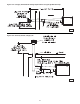
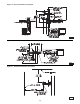
3. Remove service access panel.
4. To clean or replace the burner, remove retainer from
around manifold orifi ce, disconnect fl ame sensor and
igniter from control board, remove burner assembly
mounting screws. See Figure 22.
5. With the burner removed, wire brush the inside surfaces
of the heat exchanger.
6. Remove any dirt, dust, or other foreign matter from
the burners using a wire brush and/or compressed air.
Ensure that all parts are unobstructed.
7. Reassemble the unit heater by replacing all parts in
reverse order.
8. Complete the appropriate unit startup procedure as
given in the “Operation” section of this manual. (See
lighting instruction on the unit nameplate).
9. Check the burner adjustment.
10. Check all gas control valves and pipe connections
for leaks.
11 Check the operation of the automatic gas valve
by lowering the setting of the thermostat, stopping
the operation of the gas unit heater. The gas valve
should close tightly, completely extinguishing the fl ame
on the burner.
12. Inspect and service motor/fan assembly. To maintain
effi cient air fl ow, inspect and clean the fan blades and
guard to prevent buildup of foreign matter.
13. Check lubrication instructions on motor. If oiling is
required, add 1 or 2 drops of electric motor oil as follows:
a. Light Duty - After three years or 25,000 hours of
operation.
b. Average Duty - Annually after 3 years or 8,000 hours
of operation.
c. Heavy Duty - Annually after one year or at least 1500
hours of operation.
Never over oil the motor or premature
failure may occur!
14. Check and test the operational functions of all safety
devices supplied with your unit.
Table 7
PERIODIC SERVICE
NOTICE: The heater and vent system should be checked
once a year by a qualifi ed technician.
All Maintenance/Service information should be recorded
accordingly on the Inspection Sheet provided in this manual.
Open all disconnect switches and
disconnect all electrical and gas supplies and
secure in that position before servicing unit. Failure
to do so may result in personal injury or death from
electrical shock.
Gas tightness of the safety shut-off
valves must be checked on at least an annual basis.
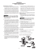
To check gas tightness of the safety shut-off valves, turn
off the manual valve upstream of the appliance combination
control. Remove the 3/32 hex head plug on the inlet side of the
combination control and connect a manometer to that tapping.
Turn the manual valve on to apply pressure to the combination
control. Note the pressure reading on the manometer, then
turn the valve off. A loss of pressure indicates a leak. If a
leak is detected, use a soap solution to check all threaded
connections. If no leak is found, combination control is faulty
and must be replaced before putting appliance back in service.
Should maintenance be required, perform the following
inspection and service routine:
1. Inspect the area near the unit to be sure that there is
no combustible material located within the minimum
clearance requirements listed in this manual.
Under no circumstances should
combustible material be located within the
clearances specified in this manual. Failure to
provide proper clearance could result in personal
injury or equipment damage from fi re.
2. Turn off the manual gas valve and electrical power
to the unit heater.
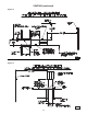
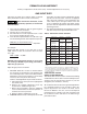
Altitude
Manifold Pressure
BTU Output
1
Natural Gas
2
Liquid Propane
3
Feet Meters Inches WC Pa Inches WC Pa Percentage
0-2,000 0-610 3.5 872 10 2,491 100%
2,001-3,000 611-915 3.2 797 9.2 2,292 96%
3,001-4,000 916-1,220 2.9 722 8.4 2,092 92%
4,001-5,000 1,221-1,525 2.7 673 7.7 1,918 88%
5,001-6,000 1,526-1,830 2.4 598 7 1,744 84%
6,001-7,000 1,831-2,135 2.2 548 6.4 1,594 80%
7,001-8,000 2,136-2,440 2 498 5.7 1,420 76%
8,001-9,000 2,441-2,745 1.8 448 5.1 1,270 72%
9,001-10,000 2,746-3,045 1.6 399 4.6 1,145 68%
Notes: 1. Deration based on ANSI Z223.1 (NFPA 54).
2. Table based on heating value of 1,050 BTU/Cu. ft. at sea level.
3. Table based on heating value of 2,500 BTU/Cu. ft. at sea level.
4. Consult local utility for actual heating value.
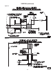
Altitude
Manifold Pressure
BTU Output
1
Natural Gas
2
Liquid Propane
3
Feet Meters Inches WC Pa Inches WC Pa Percentage
0-2,000 0-610 3.5 872 10 2,491 100%
2,001-3,000 611-915 3.2 797 9.2 2,292 96%
3,001-4,000 916-1,220 2.9 722 8.4 2,092 92%
4,001-4,500 1,221-1,371 2.8 697 7.9 1,968 90%
Notes: 1. Deration based on CGA 2.17-M91
2. Table based on heating value of 1,050 BTU/Cu. feet at sea level.
3. Table based on heating value of 2,500 BTU/Cu. feet at sea level.
4. Consult local utility for actual heating value.
High Altitude Deration - United States
High Altitude Deration - Canada