
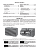
Specifications
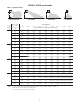


5
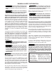
INSTALLATION
Do not install unit heaters in
corrosive or fl ammable atmospheres! Premature
failure of, or severe damage to the unit will
result!
Avoid locations where extreme
drafts can affect burner operation. Unit heaters
must not be installed in locations where air for
combustion would contain chlorinated, halo-
genated or acidic vapors. If located in such an
environment, premature failure of the unit will
occur!
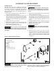
Since the unit is equipped with an automatic gas ignition
system, the unit heater must be installed such that the
gas ignition control system is not directly exposed to
water spray, rain or dripping water.
NOTICE: Location of unit heaters is related directly to
the selection of sizes. Basic rules are as follows:
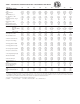
MOUNTING HEIGHT: Unit Heaters equipped with
standard fan guards must be installed at a minimum
of 8' (2.4m) above the fl oor, measured to the bottom of
the unit. For mounting heights above 8', see Table 2 to
compare unit height to heat throw distance.
AIRCRAFT HANGARS: Unit Heaters must be installed
in aircraft hangars as follows: In aircraft hangars, unit
heaters must be at least 10' (3.0m) above the upper
surface of wings or engine enclosures of the highest
aircraft to be stored in the hangar, and 8' (2.4m) above
the floor in shops, offices and other sections of the
hangar where aircraft are not stored or housed. Refer
to current ANSI/NFPA No. 409, Aircraft Hangars. In
Canada, installation is suitable in aircraft hangars when
acceptable to the enforcing authorities.
PUBLIC GARAGES: In repair garages, unit heaters must
be located at least 8' (2.4m) above the fl oor. Refer to the
latest edition of NFPA 88B, Repair Garages.
In Canada, installation must be in accordance to the
latest edition of CSA B149 “Installation Codes for Gas
Burning Appliances and Equipment.”
AIR DISTRIBUTION: Direct air towards areas of
maximum heat loss. When multiple heaters are involved,
circulation of air around the perimeter is recommended
where heated air fl ows along exposed walls. Satisfactory
results can also be obtained where multiple heaters are
located toward the center of the area with heated air
directed toward the outside walls. Be careful to avoid
all obstacles and obstructions which could impede the
warm air distribution patterns. Heat throw distances are
presented in Table 2.
Unit heaters should not be installed to maintain low
temperatures and/or freeze protection of buildings.
A minimum of 50°F (10°C) thermostat setting must
be maintained. If unit heaters are operated to maintain
lower than 50°F (10°C), hot flue gases are cooled
inside the heat exchanger to a point where water
vapor (a fl ue gas by-product) condenses onto the heat
exchanger walls. The result is a mildly corrosive acid that
prematurely corrodes the aluminized heat exchanger and
can actually drip water down from the unit heater onto
fl oor surface. Additional unit heaters should be installed
if a minimum 50°F (10°C) thermostat setting cannot be
maintained.
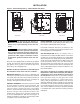
Figure 2 - Dimensional Drawing – Tubular Blower Unit Heater
Rear View
Side View
Front View
D8931B
32 1/2
A
33
L
(Discharge
Opening)
M
B
Gas Valve
Electrical Control Panel
Flue
C
G
(Discharge
Opening)
P
1 1/8
E
H
D
F
D8931B