
User manual

13
ENGLISH
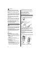
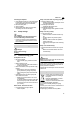
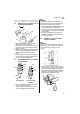
1. For selection of the largest discharge line
diameter:
cut the smaller attachment off the multi-
adapter (14).
3Note:
The best pump capacity is achieved through
selection of the largest discharge line diame-
ter.
2. Screw the multi-adapter (14) on to the el-
bow (15).
3. Screw the elbow incl. multi-adapter on to
the discharge port (16).
4. Slide the discharge line over the multi-
adapter (14) and secure with a hose
clamp.
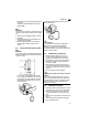
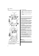
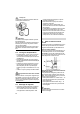
4.3 Fixing the float switch cable
3Note:
Fix the float cable such that the distance be-
tween the cable holder and the float switch is
at least 100 mm.
Form a loop with the float switch cable.
Lay the loop as illustrated over the centre
hook (18) on the cable holder and guide
the float switch cable under the two out-
side hooks (17).
The following illustration shows the fixed
float switch cable:
A Caution!
The float switch cable may be damaged.
Never pull on the float switch cable to
change its position in the cable holder!
To detach the float switch cable carry out the
steps in reverse order.
4.4 Installation instructions
Space required: approx. 50 x 50 cm.
In order for the float switch to function
properly it must be able to move freely.
Submerge the pump to no more than the
maximum immersion depth specified in
the technical data.
Install the pump such that the suction in-
lets cannot be blocked by foreign objects.
If necessary place the pump on a support
surface.
Ensure sufficient upright stability.
BRisk of electric shock from severed
cables!
Do not lift or transport the pump by the ca-
bles or the discharge hose! The cables and
the discharge hose are not designed to with-
stand the tensile stress produced by the
weight of the pump.
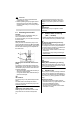
4.5 Installing the pump
1. Submerge pump at a slight angle to avoid
creating an air cushion on the underside,
which would prevent priming. Once the
pump is submerged, it can be placed up-
right.
2. Lower pump to the bottom of the fluid con-
tainer.
Use a strong rope fastened to the lifting
eye to lower the pump.
17
18