
User Manual

ENGLISHen
10
workplace and wear appropriate protective
equipment, such as respirators able to filter
microscopically small particles.
Observe the relevant guidelines for your material,
staff, application and place of application (e.g.
occupational health and safety regulations,
disposal).
Collect the generated particles at the source, avoid
deposits in the surrounding area.
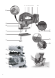
See page 2.
1 Clamping lever for securing the saw blade
2 Saw blade clamping fixture
3 Saw blade support roller
4 Saw blade
5 Anti-splintering footplate insert
6 Protective plate for attaching to the footplate
7Footplate
8 Protective rod for preventing unintentional
contact with the saw blade
9 LED working light
10
Control lever
of
chip blower
11 Switch lock/transport lock to guard against
accidental activation
12 Trigger
13 Adjustment lever for pendulum motion
14 Hexagon spanner
15 Battery pack release button
16 Battery pack*
17 Capacity indicator button
18 Capacity and signal indicator
19 Screw for adjusting the footplate
20 Curved support plate indicating preset cutting
angle
* depending on features
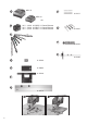
6.1 Introduce the anti-splintering footplate
insert into the protective plate (5).
Danger of injury due to the sharp jigsaw blade.
Remove the saw blade
before fitting (5) the anti-
splintering footplate insert.
Turn the machine over so that the footplate faces
upwards. Insert the anti-splintering footplate from
the front,
ensuring the following:
•
The smooth side of the footplate faces upwards.
•
The slot is facing to the rear.
If you wish to work with the protective plate attached
(see chapter Accessories 10.), fit the anti-splintering
footplate insert in the protective plate.
6.2 Inserting the saw blade
Danger of injury due to the sharp jigsaw blade.
After stopping work, the jigsaw blade may still
be hot. Wear protective gloves.
Use a saw blade that is suitable for the material
being sawn.
- Turn the clamping lever (1) forwards to the stop
and hold in place.
- Insert the saw blade (4) up to the stop. Ensure that
the saw teeth are facing forwards and the blade is
seated correctly in the groove on the saw blade
support roller (3).
- Release the clamping lever (1). (It returns to its
initial position by itself. The saw blade is now
securely tightened).
6.3 Removing the saw blade
- Turn the clamping lever (1) forward until the stop;
the saw blade is ejected as a result of spring force.
Caution: Be careful not to point the jigsaw at
anyone when removing it.
6.4 Diagonal cuts
Remove the protective plate (6)
. This part cannot be
used for making diagonal cuts.
- Slacken the screw (19).
- Slid the footplate (7) forwards slightly and turn.
- The preset angle is indicated on the curved
support plate (20) on the footplate. Adjust to
different angles using an angle gage.
7.1 Battery pack
Charge the battery pack before use (16).
If performance diminishes, recharge the battery
pack.
"Li-Power" li-ion battery packs have a capacity and
signal indicator: (18)
- Press the button (17), the LEDs indicate the
charge level.
- If one LED is flashing, the battery pack is almost
flat and must be recharged.
7.2 Removing and inserting the battery pack
To remove:
Press the battery pack release (15) button and pull
the battery pack (16) forwards
.
To fit:
Slide in the battery pack (16) until it engages.
7.3 Chip blower
Optional blower for a clear view of the cutting line.
Turn the control lever (10) on the right-hand side of
the machine.
O = Chip blower on
X = Chip blower off
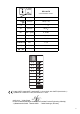
7.4 Adjusting the pendulum motion
Set the required pendulum motion using the
adjustment lever (13).
Position "0" = pendulum motion is switched off
. . .
Position "3" = maximum pendulum motion
See page 2 for recommend setting values.
The best way to determine the ideal setting is
through a practical trial.
5. Overview
6. Initial Operation
7. Use