
User Manual


ENGLISH en
7
Original instructions
We, being solely responsible, hereby declare that
these nibblers conform to the standards and direc-
tives specified on page 3.
The machine is suitable for burr-free parting,
notching and recessing of all types of sheet metal
without deformation of the material, and for
punching plastics suitable for this purpose
(appropriate thickness).
The user bears sole responsibility for damage
caused by improper use.
Generally accepted accident prevention
regulations and the enclosed safety information
must be observed.
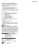
For your own protection and for the
protection of your electrical tool, pay
attention to all parts of the text that are
marked with this symbol!
WARNING – Reading the operating instruc-
tions will reduce the risk of injury.
WARNING Read all safety warnings and
instructions. Failure to follow all safety warn-
ings and instructions may result in electric shock,
fire and/or serious injury.
Keep all safety instructions and information for
future reference.
Pass on your electrical tool only together with these
documents.
Pull the plug out of the plug socket before any
adjustments or servicing are performed.
Avoid inadvertent starts: always switch the tool off
when the plug is removed from the mains socket or
if there has been a power cut.
Wear ear protectors. Exposure to noise can cause
loss of hearing.
Always wear protective goggles, gloves, and sturdy
shoes when working with this tool.
Secure the workpiece, e.g. using clamps.
Keep hands away from the cutting area.
Always switch on the machine before offering up to
the workpiece.
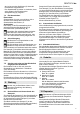
SYMBOLS ON THE TOOL:
..........Class II Construction
V ............. volts
A .............amperes
Hz ...........hertz
W............ watt
n
0
............ Stroke rate at idle speed
min.......... minutes
spm......... Stroke rate per minute
~............. alternating current
max. GA.. maximum material thickness
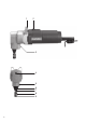
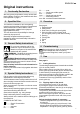
See page 2.
1 Support bracket
2 Sliding switch
3 Grub screw (for fixing the punch guide)
4 Slot in the spigot on the eccentric shaft
(for moving the punch up and down manually)
5Housing
6Punch guide
7Punch
8Die
9Spring
Before plugging in, check to see that the rated
mains voltage and mains frequency,
as stated on the rating label, match your power
supply.
See page 2.
7.1 Cutting direction
The discharge opening faces forwards when the die
(8) is in normal position.
When making cuts to one side (left or right), the
punch guide (6) (and the die (8)) can be turned 90°
to either side by loosening the grub screw (3).
After turning the punch guide (and die), screw in the
grub screw (3) until the tip engages in the
counterbore in the top (cylindrical) section of the
punch guide (6).
7.2 Dipping depth of the punch
You can move the punch (7) up and down
by turning the spigot on the eccentric shaft
(insert the screwdriver in the slot (4) on the spigot).
Correct dipping depth:
The punch (7) should dip into the die (8) as far as
possible when in the lowest position.
When in the highest position, the punch should
not protrude beyond the lower end of the punch
guide (6).
Adjust the dipping depth, if necessary:
-Unscrew the grub screw (3) on the back of the
housing (5).
- Turn the punch guide (6) (only full turns). If the
dipping depth is insufficient: turn anticlockwise.
Explanation: Turning the punch guide (6) inserts
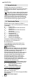
1. Conformity Declaration
2. Specified Use
3. General Safety Instructions
4. Special Safety Instructions
5. Overview
6. Commissioning
7. Use