
User Manual


ENGLISHen
8
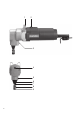
the punch (7) deep into the conrod bolt inside the
housing (5).
- Screw in the grub screw (3) so that the tip engages
in the counterbore on the punch
guide (6).
7.3 Switching On and Off
Switching on:
Push the sliding switch (2) forwards until it latches
into position. The symbol "I" then appears from
behind the sliding switch.
Switching off:
When the switch is set to on, press down the
raised rear end of the sliding switch (2)
(switch position "0").
Avoid inadvertent starts: always switch the
tool off when the plug is removed from the
mains socket or if there has been a power cut.
7.4 Cutting operation
Always switch on the machine before offering
up to the workpiece.
Apply a coating of oil to the cutting mark when
machining sheet steel and apply petroleum
when cutting sheet aluminium.
The punch (7) leaves behind a groove in the
material about 8 mm (5/16“) wide. With the cutting
head, you can rotate the machine 360° in the
material at any position, which makes it possible to
cut right-angled exterior contours (with a radius of 0
mm). The smallest radius for interior cut-outs is
4 mm (3/16“).
7.5 Cuts to a template fixed on the
workpiece
Ensure that the template is thick enough for the
overall thickness of workpiece + template to reach
4-5.5 mm (.16 to .22 inches).
The template must be clamped at a distance of
2.5 mm (.10 inches) from the contour you wish to
cut.
Guide the machine with the edge of the punch guide
(6) always resting on the template.
Pull the plug out of the plug socket before any
adjustments or servicing are performed.
8.1 Re-sharpening and replacing the punch
To remove the punch (7), loosen the grub screw (3),
pull the punch guide (6) from the housing (5) and
unscrew the punch (7) from the conrod bolt.
To re-sharpen the punch (7), grind the end face of
the punch flat (allow the grinding surface to cool!).
Whet the cutting edge slightly using an oil stone.
Replacing the punch, see Section 9. (Accessories).
Screw the punch (7) into the conrod bolt (so that the
conrod bolt can still be moved slightly in the
conrod). Slide the punch guide (6) over the punch
(7) and into the housing (5).
Check the dipping depth of the punch (7)
(see Section 7.2). and adjust if necessary
(see Section 7.2).
Secure by tightening the grub screw (3)
8.2 Replacing the die
Replace the die (8) if it becomes blunt.
Open up the spring (9) slightly and remove.
Remove the straight pin that secures the die (8) and
pull out the die (8).
Replacing the die, see Section 9. (Accessories).
Secure the die with the new straight pin supplied.
Place the spring (9) back in position and turn so that
it covers the straight pin.
8.3 Carbon brushes
If the brushes are completely worn, the machine
switches off automatically. This prevents damage to
the motor.
The carbon brushes should be replaced by the
manufacturer or a suitable specialist workshop. See
Section 10. (Repairs).
Use only genuine Metabo accessories.
If you need any accessories, check with your
dealer.
For dealers to select the correct accessory, they
need to know the exact model designation of your
power tool.
A Replacement punch
Order no. 6.30202
BReplacement die
Order no. 6.30203
CDie
Order no. 6.30204
When fitted with die 6.30204, the machine is
also suitable for cutting corrugated sheets
(up to 1.25 mm thick).
For a complete range of accessories, see
www.metabo.com or the main catalogue.
Repairs to electrical tools must be carried out
by qualified electricians ONLY!
If you have Metabo electrical tools that require
repairs, please contact your Metabo service centre.
For addresses see www.metabo.com.
You can download spare parts lists from
www.metabo.com.
Observe national regulations on environmentally
compatible disposal and on the recycling of disused
machines, packaging and accessories.
Only for EU countries: Never dispose of
power tools in your household waste! In
accordance with European Guideline
8. Maintenance
9. Accessories
10. Repairs
11. Environmental Protection