
User Manual


ENGLISHen
8
Original instructions
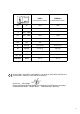
We declare under our sole responsibility: These
screwdrivers, identified by type and serial number
*1), comply with all relevant requirements of the
directives *2) and standards *3). Technical file at *4)
- see page 3.
The screwdriver is designed to insert and remove
screws and also to tighten and release nuts.
The user bears sole responsibility for any damage
caused by unspecified use.
Generally accepted accident prevention
regulations and the enclosed safety information
must be observed.
For your own protection and for the
protection of your power tool, pay
attention to all parts of the text that are
marked with this symbol!
WARNING – Reading the operating
instructions will reduce the risk of injury.
WARNING Read all safety warnings and
instructions. Failure to follow all safety
warnings and instructions may result in electric
shock, fire and/or serious injury.
Keep all safety instructions and information for
future reference.
Pass on your power tool only together with these
documents.
Pull the plug out of the plug socket before any
adjustments or servicing are performed.
Take care to avoid gas, electricity, and water
supplies!
Hold the power tool only at insulated housing parts
if there is a danger of making contact with
concealed electric cables or the supply cable.
Contact with live wires energises the metal parts of
the housing and can cause electric shock to the
operator.
Wear hearing protection when working for a longer
period of time. High noise levels over a prolonged
period of time may affect your hearing.
Note that high counter-torques are possible during
work.
USE 8: When working with max. torque, always
use the side handle supplied.
Materials that generate dusts or vapours that may be
harmful to health (e.g. asbestos) must not be
processed.
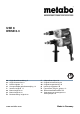
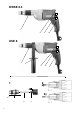
See page 2.
1 Setting collar (torque setting)
2 Side handle
*
3 Rotation selector switch
4Trigger
5 Lock button
6Stop sleeve
7Depth stop
8Tool
9 Quick-release lock
* equipment-dependent
Before plugging in check to see that the rated
mains voltage and mains frequency, as stated
on the rating label, match with your power supply.
Always install an RCD with a max. trip current
of 30 mA upstream.
6.1 Side Handle Installation (USE 8)
Open the clamping ring by turning the side handle
(2) counter-clockwise. Slide the side handle onto
the spindle collar of the machine. Tighten the side
handle at an angle as required for the application.
7.1 Switching On and Off
To start the machine, press the trigger (4).
The speed can be changed at the trigger by
pressing.
For continuous operation the trigger can be locked
with the lock button (5). To stop the machine, press
the trigger again.
7.2 Selection of Rotary Direction
Do not actuate the rotation selector switch
(3) unless the motor has completely
stopped.
Selecting the direction of rotation:
R=clockwise
L = counter-clockwise
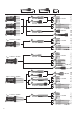
7.3 Tool Change
See page 3, Figure 1.
Remove depth stop (7). Slide the quick-change lock
(9) forwards and hold in position. Remove or insert
tool (8). Release the quick-change lock (9).
Place depth stop (7) back in position:
When fitting, turn until it snaps into place.
1. Declaration of Conformity
2. Specified Use
3. General Safety Information
4. Special Safety Instructions
5. Overview
6. Initial Operation
7. Use