Bedienungsanleitung Operating Instructions Instructions de service Gebruiksaanwijzing Instrucciones de uso 115 162 4029 / 0803 - 3.2 Invert 130/40 Invert 130/60 Achtung! Attention! Attention! Attentie! ¡Atención! Lesen Sie diese Anleitung vor der Installation und Inbetriebnahme aufmerksam durch. Carefully read through these instructions prior to installation and commissioning. Prière de lire attentivement la présente notice avant l'installation et la mise en service.
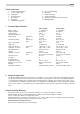
ENG Table of Contents 1 2 2.1 3 4 5 6 1 Technical Specifications Scope of Application Information Commissioning Description Operation TIG-Welding (optional) Tips for TIG-Welding Overloads Trouble Shooting Safety Information Protection against Electrical Accidents Wiring Diagram Technical Specifications Mains voltage: Mains frequency: Setting range: Stromeinstellbereich: Power input: Operating voltage: Max. current draw: Mains fuse: Duty cycle at max.
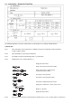
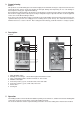
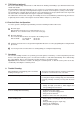
2.1 Information - Shown On Type Plate The following explanations refer to the numbered boxes shown in Figure 2.3 according to ISO/IEC 60974-1. a) Identification Box l Name and address of the manufacturer or distributor or importer and, optionally, a trade mark and the country of origin, if required Box 2 Type (identification) as given by the manufacturer Box 3 Traceability of design and manufacturing data, e.g.
b) Welding Output Box 6 Welding process Symbol e.g.: Manual metal arc welding with covered electrodes Tungsten inert-gas welding Metal inert and active gas welding including the use of flux cored wire Selfshielded flux cored arc welding Submerged arc welding Symbol for plasma cutting Symbol for plasma gouging Box 7 Symbol for welding power sources which are suitable for supplying power to welding operations carried out in an environment with increased hazard of electric shock (if applicable).
Column a) need not be used if the duty cycle (duty factor) for the rated maximum welding current is 60 % or 100 %. Column b) need not be used if the duty cycle (duty factor) at the rated maximum welding current is 100 %. c) Energy input Box 14 Energy input symbol e.g.: Input supply, number of phases (e.g. l or 3), symbol for alternating current and the rated frequency (e.g. 50 Hz or 60 Hz) Engine Motor Belt drive Box 22 Box 23 IP.. Degree of protection, e.g. IP21 or IP23.
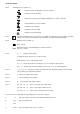
3 Commissioning Caution: This product is assembled with great care and thoroughly checked. All units undergo a computerised check before leaving the factory. Please check your machine for transport damage after unpacking. In case such damage is detected please notify your supplier immediately. Ensure that mains voltage matches the machine's rated voltage as shown on its name plate. Connect to 230/240 V AC circuit. The supply circuit need to be protected by a 16 amp time-lag fuse.
Dust, dirt and metal chips will harm any welding machine. It is of particular importance that the air ventilation for cooling is not disabled. Prior to welding the joints must be cleaned and dirt, rust, grease and paint removed. Also slag from previous welds must be completely removed. Attach earth clamp firmly to work piece, assuring good metal to metal contact. Check that all cables and connectors are in proper operating condition to ensure proper current conduction.
Welding Hints Because of the multitude of and great differences in the important points for welding only the very basic operations for the most common electrodes for low-carbon steels, the rutile or rutile cellulose electrode, are introduced here. In the case that other electrodes have to be used, the electrode manufacturers supply upon request all relevant information for the type of special electrode to be used. Always make some trial welds on scrap material.
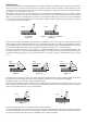
6 TIG Welding (optional) Due to the same welding characteristics as with manual arc welding, TIG welding is possible with models Invert 130/40 and 130/60. For TIG welding a TIG torch model SR 17 V (see section 11) is used, which is always connected to the negative (-) pole. The arc is started by scratching with the tungsten electrode on the workpiece (causing a short-circuit). The shielding gas is supplied directly from the pressure reducing device of the gas cylinder to the torch.
9 Safety Precautions/Accident Prevention - This Welding Machine should only be used for its intended application (TIG and manual arc welding). - Operate machine only on power supply circuits having a fully operational protective bonding circuit (earth/ground lead). - Know and adhere to all applicable local safety standards and codes. 9.1 Protection against the Risk of Electric Shock The earth cable is to be firmly attached to the workpiece, ensuring good conduction.
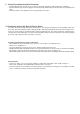
10 Wiring Diagram Invert 130/40 and 130/60 (5) (6) (4) (2) (1) Power cable (2) Switch/plug (3) Control PCB (4) Transformer (5) Diodes (6) Choke (7) Fan (3) (7) (1) 11 Exploded View Drawing and Spare Parts List TIG-Torch SR 17 V 1 2 3 4 Ø 1,0 5 Ø 1,6 6 7 8 9 10 Ø 1,0 11 Ø 1,6 12 (5) Ø 8,0 13 (6) Ø 9,5 14 1 2 3 4 5 6 7 8 9 132 712 7230 132 712 7248 132 712 7892 132 712 7078 132 712 7086 132 766 9202 132 766 9199 132 712 7256 132 717 1174 10 11 12 13 14 15 16 15 16 132 712 7132 132 712
D DEUTSCH ENG ENGLISH KONFORMITÄTSERKLÄRUNG Wir erklären in alleiniger Verantwortlichkeit, dass dieses Produkt mit den folgenden Normen übereinstimmt* gemäß den Bestimmungen der Richtlinien**.
Country; Company; Address 1; Address 2; City; Phone; Fax; E-mail Albania; Extra Industrial Goods; Rl. Fadil Rada 88; ; Tirana; (+355) 42 - 3 30 62; (+355) 42 - 3 30 62; abeqiri@t-online.de Algerie; Haddad Equipement Professionel; 98 A, Site du Lycée; ; 16012 Rouiba; (+213) 21 - 85 49 05; (+213) 21 - 85 57 72; heprouiba@hotmail.com Argentina; Metabo Argentia S.A.; Teniente Gral. Richieri 4773; ; 1702 - Ciudadela Buenos Aires; (+54) 11 - 44 88 - 9180; (+54) 11 - 44 88 - 39 89; info@metabo.com.