
Operation Manual


10
ENGLISH
ENG
Always route the connecting cable away from the
tool towards the rear.
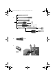
See page 3 (please unfold).
1 Tool lock
2 Switch button
3Lock
4 Rear handle
5 Trigger
6 Electronic signal indicator
7 Receiver of
Metabo CODE! Systems
(for use with
a
Metabo CODE! Key * )
8 Adjusting wheel for setting
impact force and speed
9 Additional handle
10
Hexagon ring
11
Wing nut
12 Depth stop
* not in scope of delivery
Smooth start:
The electronics system only increases impact
speeds slowly after switching on so that the chisel
or the drill retains the desired position on the
masonry. When the drill is inserted in an existing
hole, there are no jerks and jolts during start-up.
Electronic impact force and speed controller
Speed and impact frequency per minute can be
adjusted on the tool to match the application.
To reduce cracking when chiselling and drilling in
soft and brittle materials.
To produce an optimised tool setting for extremely
precise chiselling and drilling.
Turn-off carbon brushes
If the brushes are completely worn, the machine
switches off automatically.
Only KHE 75: An LED warns before the brushes
are completely worn.
Metabo CODE! System
Electronic anti-theft device at the push of a button.
With the CODE! key, which is available separately,
you can lock up your power tool and thus protect
it against misuse or theft.
Overload clutch
The overload clutch limits the maximum torque if
the tool should happen to block during operation.
This protects the gear unit and motor from over-
loading.
Before plugging in, check to see that the
rated mains voltage and mains
frequency, as stated on the rating label,
match with your power supply.
Use only extension cables with a min. cross-
section of 1.5 mm
2
. Extension cables must corre-
spond to the power consumption of the machine
(cf Technical Specifications). If a cable roller is
used, always roll up the cable completely.
7.1 Assembly of the additional handle
For safety reasons, always use the addi-
tional handle (9) supplied.
Release the additional handle by turning the
hexagon ring (10) counterclockwise. The addi-
tional handle can be moved to desired angle.
Tighten the hexagon ring (10) firmly.
The additional handle (9) must be firmly screwed
into the additional handle mount.
8.1 Depth Stop Setting
Release the wing nut (11). Set depth stop (12) to
the desired drilling depth and retighten wing nut.
8.2 Positioning, removing tool
Before inserting, clean tool shank and
apply supplied special grease (accesso-
ries: Order no. 6.31800)!
Use only SDS-max tools.
Positioning tool:
Turn tool and insert until it engages. The tool is
locked automatically.
Pull on the tool to check that it is
correctly seated.
(The tool must move a
few centimetres in axial direction.)
Removing the tool:
Pull tool lock (1) to the rear (a) in direction of arrow
and remove tool (b).
8.3 Setting operating mode
Press the lock (3) and hold in. Select the desired
operating mode by turning the switch button (2).
(Switch button must be horizontal). Release the
lock and check that the switch button has engaged.
Hammer drilling
Chiselling
5 Overview
6 Special Product Features
7 Commissioning
8Use
17026726_0107 KHE 75 KHE 55.book Seite 10 Freitag, 26. Januar 2007 8:42 08