
Operation Manual


20
ENGLISH
outlet. To do so, start the circular saw
briefly and check to see if the saw
blade turns in the direction indicated
by the arrow.
With an incorrect direction of rota-
tion, the phase sequence needs to be
corrected by a qualified electrician at
either the power outlet or the power
cable.
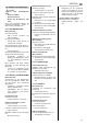
Main switch
Note:
The main switch (2) can be
blocked by a padlock to prevent unau-
thorized use.
To switch ON:
• Turn main switch (2) to "1".
To switch OFF
• Turn main switch (2) to " 0".
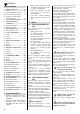
Operating mode selector
The operating mode selector (3) is actu-
ated by the key supplied. The following
operating modes can be selected:
A = Spindle moulder mode
B = Planer/thicknesser mode
C = Circular saw mode
Start/stop pushbuttons
For each operating mode separate start/
stop pushbuttons are provided.
• To switch ON:
Press the green pushbutton of the
respective operating mode.
• To switch OFF:
Press red pushbutton – each oper-
ating mode can be switched OFF by
any of the three red pushbuttons or
by the main switch.
5.1 General safety devices
Emergency-stop pushbutton
In spindle moulder mode, the red push-
button (4) functions as emergency stop
switch. In any operating mode the emer-
gency stop switch immediately shuts the
machine down. Before switching ON
again, the red pushbutton needs to be
reset by turning it counter-clockwise.
Undervoltage relay
An undervoltage relay trips in the event
of a voltage failure to prevent restarting
of the machine when the power is
restored. To switch ON again, the green
pushbutton of the relevant operating
mode must be actuated.
6.1 Setup
Danger!
Before setting the machine up:
− Switch machine OFF.
− Unplug.
− Wait until machine has come to a
complete stop.
Work area preparation
Ensure the removal of all not required
objects from the work area:
1. Saw blade and blade guard fully
retracted and covered by table
insert?
2. Cutter fence completely dis-
mounted?
3. Cutter spindle fully retracted and
covered by table rings and insert?
4. Dust chute swung under the planing
bed for thickness planing?
5. Planing beds folded down?
6. Morticing bit chuck covered?
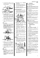
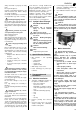
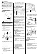
Fence installation
1. Place the fence carrier (5) on the
guide bar (6) and secure with the
star-knob screw (7).
2. Loosen lock lever (8) and adjust
jointer fence position lengthwise: the
recess in the fence extrusion (9)
must be positioned over the cutter-
block, as illustrated below.
3. Cover the part of the cutterblock
behind the jointer fence with the
cover plate (10).
Cutterblock cover installation:
1. Fasten the cutterblock's arm (11) to
the outfeed table.
2. Slide cutterblock guard extrusion
(12) in the seat on the arm of the
cutterblock cover and lock with
screw (13).
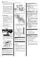
Connecting the dust collection
attachment
1. Unlock the infeed table (14) and
carefully lift it up.
2. Hang the dust chute for surface
planing with both prongs on the cut-
terblock guard plate.
3. Pull locking bolt on hinge of infeed
table out and carefully lower the
infeed table.
4. Connect a suitable dust collector to
the dust chute's suction port (15).
5. Operating Elements
2
3
A
B
C
6. Surface Planer Mode
4
5
76 8
9
10
11
12 13
14