
Operation Manual


25
ENGLISH
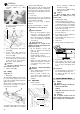
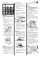
Cutting speed in m/s
Danger!
At this combination there is an
increased risk of kickback and/or tool
breakage.
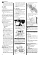
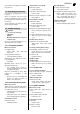
The speed is set by changing a belt:
• upper pulleys:
speed of cutter spindle 8500 min
-1
• centre pulleys:
speed of cutter spindle 6750 min
-1
• lower pulleys:
speed of cutter spindle 4300 min
-1
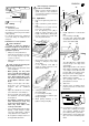
1. Open the spindle drive guard (push
guard hood (55) to bottom).
2. Loosen lock lever (56) and slacken
belt by pushing the lever (57)
towards the cutter spindle.
3. Shift belt to desired pulleys.
Danger!
The belt must always run on
pulleys that are level with each other.
4. Tighten belt by pulling the lever (57)
away from the cutter spindle.
5. Lock motor in position with the lock
lever (56).
6. Close the guard hood. The set
speed is displayed on the outside on
the guard hood.
Work area preparation
Ensure the removal of all not required
objects from the work area:
1. Saw blade and blade guard fully
retracted and covered by table
insert?
2. Fence removed?
3. Morticing bit chuck covered?
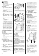
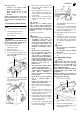
Cutter installation
1. Remove table insert and table insert
rings.
2. Loosen locking screw (58) and
crank cutter spindle with handwheel
(59) fully up.
3. To block the cutter spindle, push on
lock pin (60) – turn cutter spindle by
hand until the lock pin engages.
4. Loosen spindle nut (61) and remove
any fitted cutters and spacing col-
lars.
5. Fit new cutter and spacing collars on
the cutter spindle.
Caution!
− Observe direction of rotation of
the cutter (counter-clockwise if
viewed from top)!
− The cutter must be positioned on
the cutter spindle as far down
possible!
6. Cover the clearance zone around
the cutter spindle with table insert
rings that accommodate the cutter
head diameter.
7. Fill space between cutter and spin-
dle thread with spacing collars.
8. Tighten spindle nut, with the open
end wrench supplied, hand-tight
only.
Danger!
− Do not extend open end wrench
for tightening the spindle nut.
− Do not tighten spindle nut by stri-
king the wrench.
− Pull lock pin (60) fully out.
9. Rotate cutter spindle by hand to
see that it runs clear of the table
insert rings.
10. Crank cutter spindle fully down with
handwheel (59).
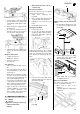
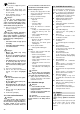
Cutter fence installation
1. Install the cutter fence's base first.
To do so, screw both bolts (62) into
the tapped holes in the machine
table.
2. Fasten the articulated arm (63) with
two each hexagon socket head cap
screw and washer to the rear of the
cutter fence's base.
3. Slide the hexagonal extension arm
(64) into the relevant bracket on the
articulated arm (63) and tighten.
4. Slide vertical holddown shoe (65)
onto the extension arm and tighten.
5. Slide lateral pressure shoe (66) onto
extension arm and tighten.
6. Connect a suitable dust collector to
the cutter fence's base.
Tenoning guard plate installation
1. Slide guard plate (67) into the
groove in the sliding carriage (68),
right up against the mitre fence and
tighten both screws on the rear of
the guard plate.
Tool
∅
Cutter spindle-
speed (min
–1
)
4300 6750 8500
180
40 m/s 64 m/s
160
57 m/s 71 m/s
140
50 m/s 63 m/s
120
43 m/s 54 m/s
100
45 m/s
55
57 56
58
59
60
61
62
63
6465
66
67 68