FC135T OWNER’S MANUAL 03/2018 WARNING: Read carefully and understand all ASSEMBLY AND OPERATION INSTRUCTIONS before operating. Failure to follow the safety rules and other basic safety precautions may result in serious personal injury. www.MetalManGear.
WARRANTY METAL MAN WORK GEAR CO EFFECTIVE JANUARY 1, 2013 LIMITED WARRANTY This warranty applies to the original purchaser and is subject to the terms and conditions listed below. This Limited Warrant y is for new equipment sold after the above date, providing coverage for defects in material and workmanship at the time it is shipped from the factory.
GENERAL SAFETY RULES WARNING: Read and understand all instructions. Failure to follow all instructions listed below may result in serious injury. CAUTION: Do not allow persons to operate or assemble this unit until they have read this manual and have developed a thorough understanding of how this unit works. WARNING: The warnings, cautions, and instructions discussed in this instruction manual cannot cover all possible conditions or situations that could occur.
material being welded, ground or electrode from another welder. -Do not weld if you are in an awkward position. Always have a secure stance while welding to prevent accidents. Wear a safety harness if working above ground. -Do not drape cables over or around your body. -Wear a full coverage helmet with appropriate shade (see ANSI Z87.1 safety standard) and safety glasses while welding. -Wear proper gloves and protective clothing to prevent your skin from being exposed to hot metals, UV and IR rays.
-Always use a helmet that covers your full face from the neck to top of head and to the back of each ear. -Use a lens that meets ANSI standards and safety glasses. For welders under 160 Amps output, use a shade 10 lens; for above 160 Amps, use a shade 12. Refer to the ANSI standard Z87.1 for more information. -Cover all bare skin areas exposed to the arc with protective clothing and shoes. Flame-retardant cloth or leather shirts, coats, pants or coveralls are available for protection.
Electromagnetic Field -Electromagnetic fields can interfere with various electrical and electronic devices such as pacemakers. -Consult your doctor before using any electric arc welder or cutting device -Keep people with pacemakers away from your welding area when welding. -Do not wrap cable around your body while welding. -Wrap MIG gun and ground cable together whenever possible. -Keep MIG gun and ground cables on the same side of your body.
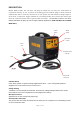
DESCRIPTION METAL MAN FC135T 115 volt input, 135 amp AC output flux core only wire feed welders is economical and easy to use. It requires no shielding gas and welds 8 gauge to 3/16" mild steel materials with .030" or .035" flux core wires on 4" or 8" spools. This unit features 2 voltage ranges, a set up chart, a cooling fan, trigger activated arc, overload protection, 8-1/2 ft torch with Tweco style series 11 replacement parts and 6 ft ground cable and clamp.
Welding Cable and Torch The welding wire is driven through the welding cable and torch to the work piece. It is attached to the drive system; the gun trigger activates the drive motor. Thermal Indicator If the duty cycle of the welder is exceeded the internal temperature will exceed safe temperatures and the machine will shut down. The Thermal overload light will come on indicating this.
3. INSTALL THE WIRE ROLLER - The wire roller has been factory installed. However, check to make certain the correct wire groove is in place to accommodate the size of wire you are using. Open the wire feed compartment. Adjust the drive roller according to the following steps, see following picture about the wire feeder structure: a. Open the door to the welder drive compartment b.
b. Installing the wire Electrical Shock • Electric shock can cause injury or death! Always turn the POWER switch OFF and unplug the power cord from the AC power source before installing wire. NOTE: - Before installing, make sure that you have removed any old wire from the torch assembly. This will help to prevent the possibility of the wire jamming inside the gun liner. - Be very careful when removing the welding nozzle. The contact tip on this welder is live whenever the torch trigger is pulled.
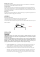
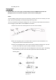
8 Inch 4 Inch g. The welder can use either 4 inch or 8 inch spools. See the following figure for additional reference. The wing nut controls the tension on the spool. h. Setting the wire spool tension. a) Turn the spool of wire with one hand. b) Increase the spool tension by tightening (turn clockwise) the wing nut while turning the spool. Turn the spool while tightening the wing nut until the spool slows down and you feel a slight drag.
p. NOW YOU CAN LET GO OF THE WIRE. q. Plug in the welder power cord and turn the welder ON. Set the Voltage switch to the voltage setting recommended for the gauge metal that is to be welded. Refer to the set-up chart on the back side of the drive compartment door. -The welding wire is electrically hot when the power is on and the torch trigger is activated. r. Set the WIRE SPEED control to the middle of the wire speed range. s.
OPERATION • High voltage danger from power source! Consult a qualified electrician for proper installation of receptacle. This cutter must be grounded while in use to protect the operator from electrical shock. • Do not remove grounding prong or alter the plug in any way. Use only the supplied adapter between the welder's power cord and the power source receptacle.
6. DISTANCE FROM THE WORK PIECE - If the nozzle is held off the work piece, the distance between the nozzle and the work piece should be kept constant and should not exceed 1/4 inch or the arc may begin sputtering, signaling a loss in welding performance. 7. TUNING IN THE WIRE SPEED - This is one of the most important parts of wire welder operation and must be done before starting each welding job or whenever the voltage setting or wire diameter is changed.
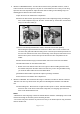
ELECTRIC SHOCK CAN CAUSE INJURY OR DEATH! To prevent ELECTRIC SHOCK, do not perform any welding while standing, kneeling, or lying directly on the grounded work piece. 8.1 Moving the torch Torch travel refers to the movement of the torch along the weld joint and is broken into two elements: Direction and Speed. A solid weld bead requires that the welding torch be moved steadily and at the right speed along the weld joint.
8.3 Welding position FLAT POSITION is easiest of the welding positions and is most commonly used. It is best if you can weld in the flat position if at all possible as good results are easier to achieve. HORIZONTAL POSITION is performed very similarly to the flat weld except that angle B (see HOLDING THE TORCH) is such that the wire, directed more toward the metal above the weld joint is to help prevent the weld puddle from running downward while still allowing slow enough travel speed.
falling into the nozzle. Angle B should be held at zero degrees so that the wire is aiming directly into the weld joint. If you experience excessive dripping of the weld puddle, select a lower heat setting. Also, the weave bead tends to work better than the stringer. 8.4 Multiple pass welding Butt Weld Joints: When butt welding thicker materials, you will need to prepare the edges of the material to be joined by grinding a bevel on the edge of one or both pieces of the metal being joined.
8.5 Spot welding There are three methods of spot welding: Burn-Through, Punch and Fill, and Lap. Each has advantages and disadvantages depending on the specific application as well as personal preference. 1. The BURN-THROUGH METHOD welds two overlapped pieces of metal together by burning through the top piece and into the bottom piece. With the burn-through method, larger wire diameters tend to work better than smaller diameters. Wire diameters that tend to work best, with the burn-through method are 0.
8.6 SPOT WELDING INSTRUCTIONS 1. Select the wire diameter and heat setting recommended above for the method of spot welding you intend to use. 2. Tune in the wire speed as if you were going to make a continuous weld. 3. Hold the nozzle piece completely perpendicular to and about 1/4 inch off the work piece. 4. Pull the trigger on the torch and release it when it appears that the desired penetration has been achieved. 5.
ELECTRICAL DIAGRAM Page 20 of 24
DIAGRAM & PARTS LIST Page 21 of 24
Reference # 1 Part# 145200013 145200017 105200040 145200014 145200016 105200410 105200411 105200036 105200412 105200032 105200413 105200031 105200042 105200030 105200414 105200415 105200416 105200417 105200418 105200025 105200024 105200008 105200419 105200420 105200421 105200422 145200015 105200041 145200001 105200423 105200424 105200425 105200009 105200006 105200005 105200001 105200029 Description Qty.
Reference # Part# 1 2 3 4 5 6 105200034 105200043 105200033 105200104 105200105 105200106 Description FLUX CORE NOZZLE .030 CONTACT TIP CONTACT TIP ADAPTER TORCH INSULATOR TORCH LINER TORCH HEAD TUBE Qty.
METAL MAN WORK GEAR CO. 1760 Prospect Ct, Suite 120 Appleton, WI 54914 888-762-4045 www.metalmangear.