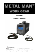
MIG140i OWNER’S MANUAL WARNING: Read carefully and understand all ASSEMBLY AND OPERATION INSTRUCTIONS before operating. Failure to follow the safety rules and other basic safety precautions may result in serious personal injury.
WARRANTY METAL MAN WORK GEAR CO EFFECTIVE JANUARY 1, 2013 LIMITED WARRANTY This warranty applies to the original purchaser and is subject to the terms and conditions listed below. This Limited Warranty is for new equipment sold after the above date, providing coverage for defects in material and workmanship at the time it is shipped from the factory.
GENERAL SAFETY RULES WARNING: Read and understand all instructions. Failure to follow all instructions listed below may result in serious injury. CAUTION: Do not allow persons to operate or assemble this Flux Core 125 until they have read this manual and have developed a thorough understanding of how the Flux Core 125 works. WARNING: The warnings, cautions, and instructions discussed in this instruction manual cannot cover all possible conditions or situations that could occur.
-Follow the instructions in this manual. -Keep welder in the off position when not in use. -Connect ground lead as close to the area being welded as possible to ensure a good ground. -Do not allow any body part to come in contact with the welding wire if you are in contact with the material being welded, ground or electrode from another welder. -Do not weld if you are in an awkward position. Always have a secure stance while welding to prevent accidents. Wear a safety harness if working above ground.
UV and IR Arc Rays The welding arc produces ultraviolet (UV) and infrared (IR) rays that can cause injury to your eyes and skin. Do not look at the welding arc without proper eye protection. -Always use a helmet that covers your full face from the neck to top of head and to the back of each ear. -Use a lens that meets ANSI standards and safety glasses. For welders under 160 Amps output, use a shade 10 lens; for above 160 Amps, use a shade 12. Refer to the ANSI standard Z87.1 for more information.
Electromagnetic Field -Electromagnetic fields can interfere with various electrical and electronic devices such as pacemakers. -Consult your doctor before using any electric arc welder or cutting device -Keep people with pacemakers away from your welding area when welding. -Do not wrap cable around your body while welding. -Wrap MIG gun and ground cable together whenever possible. -Keep MIG gun and ground cables on the same side of your body.
DESCRIPTION The Metal Man MIG 140i is a portable DC wire feed welder capable of welding with solid wire (with shielding gas) or flux core wire. It uses leading edge Inverter Technology to provide high quality welds that are crisp, clean, and consistent with plenty of power and will impress the most experienced of welders. It is powered by AC single phase 120V (110-120V), 60HZ/20amp with time delayed fuse or circuit breaker.
Welding Cable and Torch The welding wire is driven through the welding cable and torch to the work piece. It is attached to the drive system, the gun trigger activates the drive motor. Wire Speed Control Adjustment of the wire feed speed (amperage). ON/OFF Switch In the “OFF” position no power is being supplied to the unit. In the “ON” position power is supplied to the main transformer and control circuit.
2. EXTENSION CORD - We do not recommend an extension cord because of the voltage drop they produce. This drop in voltage can affect the performance of the welder. If you need to use an extension cord, it must be a size #12 or larger. Check with a qualified electrician and your local electrical codes for your specific area. Do not use an extension cord over 25 ft. in length. 3. INSTALL THE WIRE ROLLER - The wire roller has been factory installed.
NOTE: - Metal thinner than 24 gauge cannot be welded with this machine. Attempting to do so will cause burn through in the metal you are intending to weld. - Do not use rusty wire. Remove any wire that is rusty. If the whole spool is rusty, discard it and use another roll. 4.2 Installing the wire Electrical Shock Electric shock can kill! Always turn the POWER switch OFF and unplug the power cord from the AC power source before installing wire.
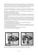
4.2.5 The welder can use either 4 inch or 8 inch spools. See the following figure for additional reference. The wing nut controls the tension on the spool. 8 Inch 4 Inch 4.2.6 Setting the wire spool tension. a) Turn the spool of wire with one hand. b) Increase the spool tension by tightening (turn clockwise) the wing nut while turning the spool. Turn the spool while tightening the wing nut until the spool slows down and you feel a slight drag.
-The welding wire is electrically hot when the power is on and the torch trigger is activated. 4.2.16 Set the WIRE SPEED control to the middle of the wire speed range. 4.2.17 Straighten the MIG torch cable and pull the trigger in the gun handle to feed the wire through the torch assembly. When at least one inch of the wire sticks out past the end of the torch, release the trigger. 4.2.18 Turn the Power Switch to the OFF position. 4.2.
6.2 Connect one end of the gas hose to the gas hose connection on the back of the welder. 6.3 Connect the other end of the gas hose to the gas hose connection on the supplied regulator/flowgauge. 6.4 Before installing the regulator, it is good practice to make certain no debris is in the gas bottle connection. Rotate the bottle so the gas connection is not pointing toward you or any other person. Turn the valve on the gas bottle clockwise and quickly close.
OPERATION High voltage danger from power source! Consult a qualified electrician for proper installation of receptacle at the power source. This welder must be grounded while in use to protect the operator from electrical shock. If you are not sure if your outlet is properly grounded, have it checked by a qualified electrician. Do not cut off the grounding prong or alter the plug in any way and do not use any adapter between the welder's power cord and the power source receptacle.
6. DISTANCE FROM THE WORK PIECE - If the nozzle is held off the work piece, the distance between the nozzle and the work piece should be kept constant and should not exceed 1/4 inch or the arc may begin sputtering, signaling a loss in welding performance. 7. TUNING IN THE WIRE SPEED - This is one of the most important parts of wire welder operation and must be done before starting each welding job or whenever the voltage setting or wire diameter is changed.
ELECTRIC SHOCK CAN KILL! To prevent ELECTRIC SHOCK, do not perform any welding while standing, kneeling, or lying directly on the grounded workpiece. 8.1 Moving the torch Torch travel refers to the movement of the torch along the weld joint and is broken into two elements: Direction and Speed. A solid weld bead requires that the welding torch be moved steadily and at the right speed along the weld joint.
8.3 Welding position FLAT POSITION is easiest of the welding positions and is most commonly used. It is best if you can weld in the flat position if at all possible as good results are easier to achieve. HORIZONTAL POSITION Is performed very much the same as the flat weld except that angle B (see HOLDING THE TORCH) is such that the wire, directed more toward the metal above the weld joint is to help prevent the weld puddle from running downward while still allowing slow enough travel speed.
falling into the nozzle. Angle B should be held at zero degrees so that the wire is aiming directly into the weld joint. If you experience excessive dripping of the weld puddle, select a lower heat setting. Also, the weave bead tends to work better than the stringer. 8.4 Multiple pass welding Butt Weld Joints When butt welding thicker materials, you will need to prepare the edges of the material to be joined by grinding a bevel on the edge of one or both pieces of the metal being joined.
8.5 Spot welding There are three methods of spot welding: Burn-Through, Punch and Fill, and Lap. Each has advantages and disadvantages depending on the specific application as well as personal preference. 1. The BURN-THROUGH METHOD welds two overlapped pieces of metal together by burning through the top piece and into the bottom piece. With the burn-through method, larger wire diameters tend to work better than smaller diameters. Wire diameters that tend to work best, with the burn-through method are 0.
MAINTENANCE • Maintain your MIG 140i. It is recommended that the general condition of any welder be examined before it is used. Keep your welder in good repair by adopting a program of conscientious repair and maintenance. Have necessary repairs made by qualified service personnel. • • Periodically clean dust, dirt, grease, etc. from your welder. Every six months, or as necessary, remove the cover panel from the welder and air-blow any dust and dirt that may have accumulated inside the welder.
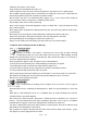
AC1 220V~240VAC AC2 EARTH SW 1 C8 R7 R1 3 R1 6 5 4 1 1 2 AC Z1 AC - + S50V B100 3 4 VC C C1 4 C4 R8 R1 1 C5 R1 4 R1 5 C6 C3 R3 R18 C1 3 C1 2 N TC1 G G R1 R20 G1 G G G2 D4 E2 D7 E1 T3 T6 R2 2 C1 8 R2 3 C1 9 1CN 4 6 7 TR1 ZBY Q1 5 4 2 1 N TC2 1CN 7 1 2 3 4 D6 D8 1 3 1 3 1 3 1 3 D1 D2 C2 C1 0 POW ER LED ALA RM LED 2 4 2 4 2 4 2 4 R9 R1 2 3 3 D3 T1 T4 1 2 3 4 5 6 7 8 1 2 2CN 5 G1 E1 G2 E2 D9 1 L2 + O G HE1 1 2 3 4 C C E E 3
DIAGRAM & PARTS LIST Page 22 of 24
Reference # Description Part Number Qty. 1 Handle 2.05.05.970 1 2 Case cover, enclosure 1.1.01.02.0338-M 1 3 Gas Valve connector 1.1.01.05.3023 1 4 Electric Cable Clamp 2.05.05.200 1 5 Power Cord 1.2.07.01.2884 1 6 Main Switch 2.07.80.001 1 7 Fan 1.2.07.02.3854 1 8 Back Panel 1.1.01.03.1651 1 9 Wire feeder wiring 2.03.30.723 1 10 Main PC Board 1.1.05.02.0502 1 11 Control Board 1.1.05.02.0503 1 12 Sheet metal case base 1.1.01.04.
Distributed by METAL MAN WORK GEAR COMPANY 1760 PROSPECT CT #113 APPLETON WI 54914 www.metalmangear.