
Full Product Manual


Page of 24
8
Welding Cable and Torch
The welding wire is driven through the welding cable and torch to the work piece. It is attached to
the drive system, the gun trigger activates the drive motor.
Wire Speed Control
Adjustment of the wire feed speed (amperage).
ON/OFF Switch
In the “OFF” position no power is being supplied to the unit. In the “ON” position power is supplied
to the main transformer and control circuit.
Wire Compartment
Open the wire compartment door, and then you can see the wire feeder and spool holder.
Power Cord
The power cord connects the welder to the 120 volt power supply. Plug the 15 amp plug into a 120
volt/20 amp receptacle to supply power to the welder.
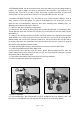
ASSEMBLY
INSTALLING THE HANDLE
1. Line up the holes in the handles with the holes on the top of the welder.
2. Place a lock washer then a washer onto the welder handle screws.
3. Insert screws with the washers through the holes on the welder handle and into the top of the
welder and tighten.
INSTALLATION
1. POWER REQUIREMENT - AC single phase 120V (110-120V) 60 HZ fused with a 20 amp time
delayed fuse or circuit breaker is required. DO NOT OPERATE THIS UNIT if the ACTUAL power
source voltage is less than 105 volts AC or greater than 132 volts AC.
Electrical Shock
High voltage danger from power source! Consult a qualified electrician for proper
installation of receptacle. This welder must be grounded while in use to protect the
operator from electrical shock.
Do not remove grounding prong or alter the plug in any way. Do not use any adapters
between the welder's power cord and the power source receptacle. Make sure the
POWER switch is OFF when connecting your welder's power cord to a properly
grounded 115 VAC, 60 HZ, Single Phase, 20 Amp input power supply.
Front