
Installation Guide


1
U
L
®
LISTED
CM
I
N
T
E
R
T
E
K
W
a
r
n
o
c
k
H
e
r
s
e
y
CUS
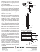
4”
5”
8-3/4” x 8-3/4”
10-5/8” x 10-5/8” 8-3/4” x 8-3/4”
10-1/8” x 10-1/8” 14-1/2” x 14-1/2” 10-1/8” x 10-1/8”
DIRECT-TEMP®
METALBEST DIRECT VENT
SYSTEM
Selkirk MetalBest DIRECT-TEMP Direct Vent system is
designed for use only with direct vent gas fired appliances
certified for use with DIRECT-TEMP, in accordance with
applicable ANSI and/or CSA gas appliance standards.
DIRECT-TEMP is listed by UL and Warnock Hersey/ITS for use
in Direct Vent Gas Appliance Systems.
CAUTION - Do not begin installing this product until you have
thoroughly read the appliance and vent system installation
instructions. Failure to comply with these instructions may lead
to hazardous conditions. Never substitute any part of the
DIRECT-TEMP Direct Vent system with components of other
systems or with any field fabricated parts. Do not modify any
part of this system unless specifically directed to do so in these
instructions. Follow the appliance manufacturers
recommendations for flue gas or intake restrictions. Contact
Local Building or Fire Officials about restrictions and
installation inspection in your area.
GENERAL USE:
Use DIRECT-TEMP only on Direct Vent gas appliances
certified for use with DIRECT-TEMP Direct Vent system.
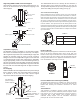
Joint Connection:
The pipe and elbows are assembled by inserting the outlet
(male) end of a length of pipe or elbow into the inlet (female) end
of an adjacent length of pipe or elbow. Make sure the outlet end
is fully seated within the inlet end of the adjoining section and
the gasket, located on the inner liner of the inlet section is fully
enclosed by the inner liner of the outlet of the
adjoining section. Push in the Lock Tab such that it becomes
seated within the inward groove of the adjoining section. This
locks the joint in place (see Figure 2).
Supporting DIRECT-TEMP: Vertical Support
Vertical Installations can be supported by two methods.
CAUTION: WEAR GLOVES WHILE
HANDLING SHEET METAL PARTS TO
AVOID PERSONAL INJURY. SHARP
EDGES OR PROJECTIONS CAN CUT YOU.
Failure to follow the installation instructions could cause
FIRE, CARBON MONOXIDE POISONING, OR DEATH. If you
are unsure of installation requirements, call the Phone
Number listed on the instructions or sizing handbook.
! WARNING
Framing Dimensions Table 1
Use of Sealant:
It is not required to apply or use sealant on the inner liner of
DIRECT-TEMP. For outer wall joint sealing considerations
follow appliance manufacturer recommendations.
Clearance to Combustibles:
Maintain proper minimum airspace clearances to combustibles
as specified by the Appliance Manufacturer’s instructions. Do
not place anything including any type of insulation in this
required air space.
Appliance Adapter:
The Appliance Adapter (AA) adapts DIRECT-TEMP to most direct
vent appliances incorporating outlet collars configured to receive
most common 4” (ID) by 6-5/8” (OD) or 5” (ID) by 8” (OD) “Twist
Lock” style, direct-vent systems.
The adapter incorporates two indentations on the outer wall of the
inlet end, which are designed to “Twist Lock” into place upon
attachment to the appliance outlet. Align the adapter indentations
with the entry slots of the appliance outlet and slide together. Turn
the adapter clockwise approximately one-quarter turn to lock in
place. The outlet end of the adapter is standard DIRECT-TEMP
construction.
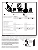
Installing DIRECT-TEMP:
There are two basic types of termination options for Direct Vent
Systems. Vertical Terminations (Fig 1a), and Horizontal
Terminations (Figs 1b and 1c).
Reference the Appliance Manufacturer’s installation
instructions to determine the type and limitations applicable to
the appliance being installed.
Ceiling Support(CS)
Firestop (FS)
Cathedral Ceiling
Support (CCS)
Wall Thimble (WT)
Model DT
Diameter
To install:
1) Determine whether the length of pipe fits the appliance outlet by
attempting to engage the parts. If the parts engage smoothly,
proceed to step 2. If obstructions, interference or loose fit is noted,
contact the appliance manufacturer or Selkirk MetalBest with the
dimensions of the appliance outlet.
2) Slide the length of pipe over the appliance outlet a minimum of
1 1/2” and screw to the appliance outlet collar using a minimum of
two #8 X 1/4” sheet metal screws.
For connection of Direct-Temp to units with 4”x7” flue outlets, the
following methods have been approved:
-Install the Universal/Napoleon Appliance Adapter 4DT-AAN.
-Connect a standard Direct-Temp pipe length (do not use an
adjustable length in this application) a minimum of 1-1/2” over the
flue outlet. The outside of the Direct-Temp Length will fit inside the
flue outlet. Secure with a minimum of two #8x1/4” sheet metal
screws and seal with hi-temp silicone.
For units factory equipped with appliance adapters from other
brands of Direct Vent systems, it is permissible to simply slide a
length of DT pipe over the appliance adapter. Secure with a
minimum of two #8x1/4” sheet metal screws and seal with hi-temp
silicone.
Gasket
Inlet End
Outlet End
To Termination
Lock Tab
To Appliance
FIG. 2 JOINT CONNECTION
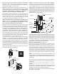
FIG. 3 CEILING SUPPORT
Ceiling Support
Collar
Ceiling Support
Plate
Trim Plate