
Installation Guide


3
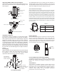
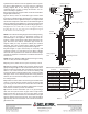
FIG. 7a
FIG. 7b
Reducer
4DT
5DT
5DT-R4
(Reducer)
The Rubber Boot Flashing Kit is available as an option for passing
the Model DT through corrugated or metal roofs. Reference the
Rubber Boot Flashing Kit Installation Instructions for further
details.
Two Part Square
Trim Plate
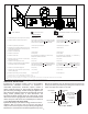
FIG. 5 OFFSET SUPPORT
Offset Support Collar
Nail to Top of
Framing
Offset Support Strap
Support Box
Support Box
Collar
FIG. 4 SUPPORT BOX
Fire Stop (FS)
placed on Top of
Framed Opening.
Maintain at Least
Minimum Clearance to
Combustibles, Wires
and Insulation.
Attic Framing
(no floor)
FIG. 6 FIRESTOP SPACER
Adjustable Length (AJ)
An Adjustable Length is available to accommodate installa-
tions where non-standard lengths are necessary. The Adjust-
able Length telescopes down over a standard length of pipe and
provides an extension range of 3-1/2" to 10-1/2". Install by
sliding the inlet end of the Adjustable Length over the outlet end
of a standard length of pipe. After positioning the Adjustable
Length appropriately, secure it to the standard length with (2)
#8 x 1/4” sheet metal screws (provided). Seal the area between
both the top and bottom of the Adjustable Length outer wall and
the outer wall of the standard length with an approved silicone
sealant.
Fire Stopping
DIRECT-TEMP must be firestopped wherever it passes through
floors, ceilings, or walls. The only location where a firestop is
not required is at the roof level. Both vertical support
components with Trim Plates provide for firestopping.
Reducer (5DT-R4)
When permitted by the appliance manufacturer, the Reducer (5DT-
R4) can be used to downsize from 5” DT to 4” DT pipe. The
Reducer should only be installed in the vertical orientation and is
connected to the DT pipe sections using the standard push tab
locking method. Refer to the appliance manufacturer’s instruc-
tions for limitations. (See Figs 7a and 7b)
JUSI Insulation is available to provide a barrier against cold air
infiltration and also provides additional protection against radiant
heat from the vent. The JUSI is installed in a wall or roof cavity in
conjunction with a Wall Thimble, Attic Insulation Shield or
Cathedral Ceiling Support. See the Installation Instructions
packaged with the JUSI for further details.
Universal Rubber Boot Flashing Kit (URBFK)
JUSI Insulation
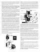
Attic Insulation Shield (AIS)
Where Model DT enters and attic space, the vent should be
protected from the known fire hazards of insulation or combus-
tible materials. An enclosure can be built around the vent or an
Attic Insulation Shield can be installed to ensure the minimum
air space is maintained. For proper installation, the attic open-
ing should be fully framed to the specified framing dimensions
found in Table 2. The square base of the AIS is placed on the
framed opening around the vent, and the AIS spacer tabs seated
within the framed opening. Nail the AIS base to the framing with
at least 2 nails per side. The AIS allows for a depth of insulation
up to 10 inches.
Supporting DIRECT-TEMP: Horizontal Support
Horizontal runs of Direct-Temp should be supported every 4 ft.
This can be done with the use of plumbers strapping or the
Offset Support.
Table 2
8.75” x 8.75”
10.125” x 10.125”
Framing Dimensions
Diameter
4” x 6-5/8”
5” x 8”
Attic Insulation Shield
The Wall Thimble also acts as a firestop. At other locations, a
Firestop Spacer (FS) should be installed. In the attic the
firestop should be placed on top of the joist framing to prevent
debris from falling into the joist framing (see Fig. 6).