
Installation Guide


5
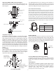
6) Install the Horizontal Termination to the exterior wall using 4
all purpose screws through the holes located at each corner of
the termination. Make sure the arrow (embossed on the front of
the termination) is pointing up (see Fig. 10 ). If the house has
vinyl siding, a Vinyl Siding Standoff (VS) must be installed prior
to installing the Horizontal Termination. Refer to the Appliance
Manufacturer to determine if one is recommended. Attach the
Vinyl Siding Standoff to the exterior side of the wall (making
sure it is level and centered with respect to the opening) with
screws (provided) at each corner of the Standoff. Attach the
Horizontal Termination to the standoff (see FIG. 11).
If the wall is brick or concrete, and contains no combustible
material, a 7" round penetration hole is adequate. The Wall
Thimble is not required. The perforated straps of the Horizontal
Termination provide a method of attachment. These can either
be threaded through the opening or Wall Thimble (if used) and
screwed to the pipe or removed with a pair of tin snips if not
used. Use proper masonry fasteners to attach the Horizontal
Termination to the wall.
2) After positioning the appliance, determine where the vent
pipe will pass through the ceiling. This can be done by using a
plum bob or a small weight attached to a string. Hold the plum
bob from the ceiling moving it until it lines up with the centerline
of the outlet of the appliance. Mark the position on the ceiling.
NOTE: Frame openings to the dimensions specified in the
Framing Table for the Cathedral Ceiling Support Box (CCS), the
Ceiling Support (CS) and wherever the Firestop Spacer (FS) is
being used.
3) Cut and frame the appropriate sized square hole through the
ceiling. Repeat the process for other ceiling penetrations as
necessary.
4) Determine and mark the roof penetration in the same
manner.
5) Cut a hole in the roof at this point large enough to satisfy all
clearance-to-combustible requirements as specified by the
appliance manufacturer’s installation instructions.
6) Install the Ceiling Support or Cathedral Ceiling Support Box
Assembly, as appropriate.
5) If required, install the outside half of the Wall Thimble (WT)
through the opening and screw or nail in place. (See FIG. 9)
Seal around the perimeter of the thimble face plate on the
exterior wall using an RTV Silicone Sealant to provide
protection from possible rain infiltration (see FIG. 9).
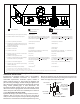
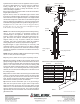
Window Well
Snorkel Termination
Grade Level
Sloped Away
From Building
12” Minimum Clearance above
Grade Level to Air Intake
FIG. 12
Adequate
Drainage as per
Local Codes
Maintain
2” Clearance
Below Snorkel
enclose the Snorkel within a wall or other type of enclosure and
do not back fill. Ensure that grade level slopes away from the
building. See FIG. 12 for details.
NOTE: The Wall Thimble accommodates wall thicknesses
of 4 1/2" to 7 1/2". If a larger range is needed due to a
thicker wall, it is permissible to field fabricate a metal
sleeve extension and attach it to the shields.
NOTE: As a general rule the Wall Thimble is optional in the U.S.
However, there may be some manufacturers that require it. Contact
appliance manufacturer for information if uncertain.
When installed
in Canada, a Wall Thimble is required on installations in
which the vent passes through a combustible wall.
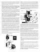
VERTICAL INSTALLATION: (See FIG. 13)
1) Determine the location of the appliance. Choose a location
which provides adequate clearance from obstacles such as
electrical wiring, conduit, framing members, plumbing pipe, etc.
NOTE: If a vertical rise is necessary on the exterior side of the
building, a 14” and 36" Snorkel Termination (ST) is available.
Follow the installation procedures for Horizontal Terminations.
If the Snorkel Termination is to be located below grade, a
window well is recommended with adequate and proper
drainage as per local codes. Leave 2” clearance below snorkel
to prevent water from entering the Snorkel Termination. Do not
7) If a Wall Thimble is used, push the pipe (which is connected
to the appliance) carefully through the Wall Thimble until the
DIRECT-TEMP pipe becomes fully engaged with the Horizontal
Termination. If no thimble is used, place the Trim Plate (TP) on
the DIRECT-TEMP pipe. Carefully push the DIRECT-TEMP
pipe through the wall until fully engaged with the Horizontal
Termination. Secure the Trim Plate to the wall.
4) Frame an opening to the dimension specified in the Framing
Dimension Table 1. Ensure that the centerline of the pipe lines
up with the center of the prepared opening unless otherwise
specified by the appliance manufacturer.
NOTE: The Vinyl Siding Standoff is not required for a Snorkel
Termination (See FIG. 12) application.
FIG. 11
FIG. 10
Horizontal
Termination
Vinyl Siding
Standoff
Horizontal
Termination