
Installation Guide

RULES FOR SAFETY DURING INSTALLATION
1. Read all installation sheets. Look for them in the cartons, or ask your
dealer for a complete set or download from www.Selkirkcorp.com. Keep the
instructions handy and save them for future reference.
2. Check your local building or fire code for all requirements affecting the
fuel-burning appliance and its chimney.
3. Obtain a building permit for both the appliance and the chimney. Contact
local building or fire officials about restrictions and installation inspection in
your area.
4. Be very careful around electrical wiring and be sure it is secured at least
2 inches away from any part of the chimney. If wiring must be relocated,
hire a professional electrician.
5. Be sure that ladders are in good condition and always rest on a level firm
surface.
6. Wear cut resistant gloves when handling sheet metal parts with sharp
edges.
7. Be sure that electrically powered tools are properly grounded.
WHEN INSTALLING YOUR CHIMNEY AND
WOODBURNING STOVE OR
FIREPLACE SYSTEM, REMEMBER . . . SAFETY FIRST
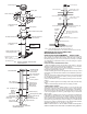
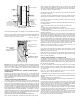
Round Top (CT)
Storm Collar (SC)
Chimney Pipe
Locking Band (LB)
or Screws
Chimney Pipe
Attic Insulation Shield (AIS)
Fire Stop/Joist Shield (JS)
Opening Framed On
All Four Sides
Locking Band (LB)
or Screws
Chimney Pipe
CHIMNEY MUST BE
ENCLOSED
Finish Support (FSP) or
Ceiling Support (CSP)
Dripless Smoke Pipe Adapter
(DSA) or (DSAC)
6”, 7”, 8” only or 5”-14” Chimney
Pipe Adapter (CPA)
FIG.1 VERTICAL CHIMNEY THROUGH ONE
STORY AND ATTIC
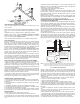
Combustible Wall
Min. Clearance
To Combustibles
2”
2”
Min. Thru Wall 4-1/2”
MetalBest
Chimney
Section
Wall Thimble
(IWT) Shield
Wall Thimble (IWT)
Face Plate
Lag Screws
Into Structure
FIG. 2 INSULATED TEE THROUGH
COMBUSTIBLE WALL
Wall Band (WB)
Every 8 Feet If
Not Enclosed
Use Locking Bands
(LB) on All Joints
Full Enclosure
Recommended.
Both Indoors
and Outdoors
Insulated Tee (IT)
Wall Support Kit (WSK)
Capped Cleanout and
Retainers
Support Bracket
Pad
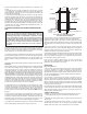
Round Top (CT)
Storm Collar (SC)
Flashing (AF) or (TF)
Roof Shield with TF
Interior Resupport (IR)
Full Enclosure or Attic
Insulation shield
Insulated Elbow (EL)
MAXIMUM
OFFSET
AT 30°
ANGLE
30°
Firestop/Joist Shield (JS)
Below Framing
Maximum inclined Length:
96” unless resupported at
48” intervals
Full Enclosure,
2” Minimum Air Space Clearance
Finish Support (FSP) or
Ceiling Support (CSP)
FIG. 3 THIRTY DEGREE OFFSET WITH ENCLOSURE AT 2”
CLEARANCE (MAXIMUM OF TWO SEPARATE OFFSETS PER SYSTEM)
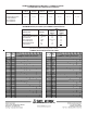
CHIMNEY HEIGHT AND SIZE
These instructions contain a ''Selector Chart" so you can pick the exact
combination of length increments. A chimney for one or more gas appli-
ances must conform to size and height recommendations in the "MetalBest
Gas Vent and Chimney Sizing Handbook." Heights above the roof as given
in the next paragraph are minimum; greater heights may be needed for
reasons given.
Before beginning installation of the chimney, be sure that the selected size
is adequate for the appliance and the selected height of the Chimney
Round Top termination is high enough to conform to building code require-
ments. Chimneys are required to extend at least 3 feet above the highest
point where they pass through the roof of a building, and at least two feet
higher than any portion of a building within 10 feet. (National Fire Protection
Association Standards Nos. 31, 54, and 211.) See Fig. 4.
You may well have a basic knowledge of carpentry and the use of hand
tools. However it is important that you also review the rules of safety on
the following pages. If you have any doubt about your ability to complete
your installation in a workmanlike manner, you should arrange for a profes-
sional installation.
Attic
Area
Insulated Elbow (EL)
Pem-Studs and Nuts
Model MCS
Chimney Section
NOTE: As stated in NFPA 211, do not install a connector or chimney that is
smaller in diameter than the outlet collar of a solid-fuel burning appliance.
Flashing (AF)