
Owner manual


5
Ensure foam packing is in place to protect electrical leads from vibration. Be sure to fit the
rubber gasket or o-ring into place prior to installing the terminal box lid to ensure a watertight seal.
Proper thermal overload selection for the vibrator's starter should be based on either:
1) Full load current rating as indicated on the unit's nameplate; or
2) Actual operating current (if lower).
(For further technical specifications on vibrator electrical data, please refer to APPENDIX A - Tables
A-1 and A-2).
3.2.2 Twin Vibrator Applications
When twin vibrators are used on one machine, it is imperative that both vibrators start and
stop at the same time. If one vibrator has an overload, both must shut off at the same time. One
push-button should control both starters.
3.2.3 Thermistor Wiring
Invicta vibrators (models BL 24 – BL 75) are equipped with PTC (Positive Temperature
Coefficient) sensors, i.e., thermistors, installed in each winding phase. Utilizing this feature is highly
recommended. These sensors (to be used in conjunction with an electronic control module) will provide
motor protection against thermal overheating. The control module interlocks the thermistors within the
windings to the starter control circuit. Please refer to Figure 4 on the following page for proper connection
of this safety feature.
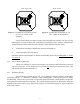
T1
T2
W2 U2 V2
U1
V1 W1
L-1
L-2 L-3
L-1
U1
W2
L-2
V1
L-3
W1
T2
T1
V2U2
STAR - 460 or 575 Volts DELTA - 230 Volts
Figure 2: Terminal box connections for 460
or 575 Volt 3 Phase, 60 Hz
operation.
Figure 3: Terminal box connections for 230
Volt, 3 Phase, 60 Hz operation.