
Manual


Operating Instructions – MOVIMOT® MM03C - MM3XC
155
13
IEC design with connection voltages 380...500 VAC
Technical Data with Integrated AS-Interface
13 Technical Data with Integrated AS-Interface
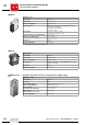
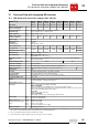
13.1 IEC design with connection voltages 380...500 V
AC
MOVIMOT
®
type MM 03C-
503-30
MM 05C-
503-30
MM 07C-
503-30
MM 11C-
503-30
MM 15C-
503-30
MM 22C-
503-30
MM 30C-
503-30
MM 3XC-
503-30
Part number 824 355 7 824 356 5 824 357 3 824 358 1 824 359 X 824 360 3 824 361 1 824 362 X
Apparent output power at
V
mains
= 380...500 V
AC
P
rated
1.1 kVA 1.4 kVA 1.8 kVA 2.2 kVA 2.8 kVA 3.8 kVA 5.1 kVA 6.7 kVA
Connection voltages
Permitted range
V
mains
3 x 380 V
AC
/ 400 V
AC
/ 415 V
AC
/ 460 V
AC
/ 500 V
AC
V
mains
= 380 V
AC
-10 % ... 500 V
AC
+10 %
Supply frequency f
mains
50 Hz ... 60 Hz ± 10 %
Rated system current
(at V
mains
= 400 V
AC
)
I
mains
1.3 A
AC
1.6 A
AC
1.9 A
AC
2.4 A
AC
3.5 A
AC
5.0 A
AC
6.7 A
AC
8.6 A
AC
Output voltage V
out
0...V
mains
Output frequency
Resolution
Operating point
f
out
2...100 Hz
0.01 Hz
400 V at 50 Hz / 100 Hz
Rated output current I
N
1.6 A
AC
2.0 A
AC
2.5 A
AC
3.2 A
AC
4.0 A
AC
5.5 A
AC
7.3 A
AC
9.6 A
AC
Motor power S1
P
mot
0.37 kW 0.55 kW 0.75 kW 1.1 kW 1.5 kW 2.2 kW 3.0 kW
3.0 kW
Motor power S3 25 % cdf 4.0 kW
PWM frequency 4 (factory setting) / 8 / 16
1)
kHz
1) 16 kHz PWM frequency (low-noise): When DIP SWITCH S3/3 = ON, the units operate with a 16 kHz PWM frequency (low noise) and switch
back in steps to lower switching frequencies depending on the heat sink temperature.
Current limitation I
max
Motor: 160 % with 댴 and 쑶
Regenerative:160 % with 댴 and 쑶
Maximum motor lead
length
15 m when mounting the MOVIMOT
®
frequency inverter close to the motor (with SEW hybrid
cable and option P2.A)
External braking resistor R
min
150 Ω 68 Ω
Interference immunity Meets EN 61800–3
Interference emission Meets EN 61800–3 and class A limit to EN 55011 and EN 55014
Ambient temperature ϑ
amb
-25 °C...40 °C (P
rated
reduction: 3 % I
N
per K to max. 60 °C)
2)
2) -25 °C...40 °C with S3 25% ED (up to 60 °C with S3 10 % ED)
Climate class 3 K3
Enclosure
(motor-dependent)
IP54, IP55, IP65, IP66 (options, specify when ordering)
IP67 (only available for inverters with terminal box)
Operating mode DB (EN 60149-1-1 and 1-3), S3 max. cycle duration 10 minutes
Cooling type (DIN 41 751) Self-cooling
Altitude h ≤ 1000 m (P
rated
reduction: 1 % per 100 m starting at an altitude of 1000 m, see also the section
"Electrical Installation – Installation Instructions")
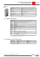
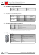
Power supply to control
electronics
AS-i
29.5 V - 31.6 V (AS-i power supply to EN 50295)
Optional AUX-PWR
24 V ± 25%, EN61131-2, residual ripple max. 13%, input capacitance \100 µF
A PELV (Protective Extra Low Voltage) power supply to IEC 60364-4-41 with safe isolation is man-
datory for the AUX-PWR auxiliary power supply.
I
E
only AS-i
≤ 200 mA
3)
(typ. 120 mA at 30 V)
I
E
AS-i + AUX-PWR
≤ 50 mA (typ. 30 mA at 30 V) + 200 mA
3)
(typ. 120 mA at 24 V)
3) The current increases by the demand of the connected sensors\ (max. 100 mA)
Control input AS-i +
AS-i -
Connection of AS-i data line
Connection of AS-i data line
Sensor connection
(maximum sensor line length
\15 m)
Tl. DI2
Tl. DI3
Tl. 0V
Tl. 0V⊥
External sensor input
External sensor input
24 V for sensor supply
Reference potential for sensor supply
Diagnostic interface Modular jack 4/4 (RJ11)
P
i
f
kVA
Hz
n