
Manual

Operating Instructions – MOVIMOT® MM03C - MM3XC
67
7
Selectable special functions MM..C-503-00
Startup of Standard Design
Bus operation
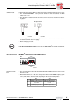
Mechanical brake controlled by MOVIMOT
®
:
• Terminals 13, 14 and 15 are assigned to the brake coil of the mechanical brake at
the wiring board of MOVIMOT
®
.
• The new function "Brake applied at down ramp" is introduced. Bit 9 in the control
word is assigned with this function as virtual terminal according to MOVILINK
®
pro-
file.
• As soon as bit 9 is set during the down ramp, MOVIMOT
®
applies the brake and in-
hibits the output stage.
• If the motor frequency is lower than the stop frequency, the brake is applied indepen-
dent of the status of bit 9.
• The relay is switched as ready relay (standard function).
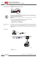
Mechanical brake controlled by relay output:
• A braking resistor (BW..) must be connected to terminal 13 and 15 at the wiring board
of MOVIMOT
®
, terminal 14 is not assigned.
• The relay functions as brake control relay so that the ready signal function is no long-
er available (it is imperative that you observe section "Use of relay output with special
function 7 + 9" starting on page 75).
• The new function "Brake applied at down ramp" is introduced. Bit 9 in the control
word is assigned with this function as virtual terminal according to MOVILINK
®
pro-
file.
• As soon as bit 9 is set during the down ramp, the relay output applies the brake and
MOVIMOT
®
inhibits the output stage.
• If the motor frequency is lower than the stop frequency, the brake is applied indepen-
dent of the status of bit 9.
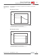
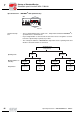
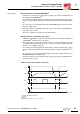
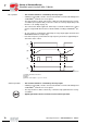
"Brake control in bus operation" flowchart:
05319BXX
[1] Enable terminals/control word
[2] Speed
[3] Bit 9
[4] Brake control signal: 1 = open, 0 = closed
[1]
[2]
[3]
[4]
1
0
n
1
0
1
0
t
t
t
t
00
I