
Installation Instructions

Instruction Manual/Instrucciones/Directives
Questions?/¿Preguntas?/Questions ? 1-800-334-6871 ConsumerProducts@cooperlighting.com
1
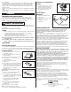
7. Locate the ballast linear disconnect
(orange) connector within fixture.
8. Grip black supply wire firmly and push conductor
into port marked with black circle on the
connector (Fig. 3).
9. Grip white supply wire firmly and push conductor
into opposite port of the connector.
10. Use only one conductor per port and assure that
no copper is exposed on inserted wires.
11. Re-attach access plate to fixture.
Notice: The wire insertion side of this product is listed for
ONE TIME USE ONLY. DO NOT REMOVE.
Flex Installation / If Required
1. To insert access plate, rotate until
leading end is inside the wireway (Fig. 4).
2. Fold into horizontal position and slide forward into
locking position.
Lens Installation / Maintenance
1. Insert corners of lens in frame (Fig. 5).
2. Slide remaining sides of lens in place.
3. Slide lens clip on ends.
2-YEAR LIMITED WARRANTY
THE FOLLOWING WARRANTY IS EXCLUSIVE AND IN LIEU OF ALL OTHER WARRANTIES,
WHETHER EXPRESS, IMPLIED OR STATUTORY INCLUDING, BUT NOT LIMITED TO, ANY
WARRANTY OF MERCHANTABILITY OR FITNESS FOR ANY PARTICULAR PURPOSE.
Cooper Lighting, LLC (“Cooper Lighting”) warrants to customers that, for a period of three
years from the date of purchase, Cooper Lighting’s products will be free from defects in
materials and workmanship. The obligation of Cooper Lighting under this warranty is expressly
limited to the provision of replacement products. This warranty is extended only to the original
purchaser of the product. A purchaser’s receipt or other proof of date of original purchase
acceptable to Cooper Lighting. This is required before warranty performance shall be rendered.
This warranty does not apply to Cooper Lighting products that have been altered or repaired or
that have been subjected to neglect, abuse, misuse or accident (including shipping damages).
This warranty does not apply to products not manufactured by Cooper Lighting which have
been supplied, installed, and/or used in conjunction with Cooper Lighting products. Damage to
IMPORTANT SAFETY INSTRUCTIONS
This fixture must be grounded and installed in accordance with local and national electrical
codes, by a person familiar with construction and operation of the product and the hazards
involved. Manufacturer assumes no responsibility for the improper installation or application
of this lighting fixture.
Warning risk of fire and electrical shock. Most dwellings built before 1985 have supply wire
rated 60˚C. Consult a qualified electrician before installation.
Notice: USE Minimum 90˚C supply conductors.
CAUTION
• Remove fixture from carton with care to avoid possible cuts and abrasions from raw
edges. Please read complete detailed installation instructions enclosed prior
to installation.
• Risk of burn. Disconnect power and allow fixture to cool before changing bulb or
handling fixture.
Notice: Green ground screw provided in proper location. Do not relocate.
Notice: Lamps contain mercury, dispose according to local, state, or federal laws.
For more information, visit: www.lamprecycle.org.
INSTALLATION INSTRUCTIONS
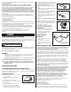
Troffer Grid-lock Feature
1. The grid lock feature is built into the housing. Bend
the tab 90 degrees, lay the fixture into the grid and
rotate either way until it engages with the T grid.
There is no need to open the fixture to use
this feature (Fig. 1).
Wiring Fixture
1. Wiring must comply with all applicable
electrical codes.
2. Turn of power before installing wiring.
3. Strip wire to 3/8” (9, 5 mm).
4. Remove access plate from backside of Troffer.
5. Remove K.O. in access plate.
6. Insert wires into removed K.O. hole. Take
ground wire and wrap it around head of green
ground screw provided in the access plate.
This wire should be wrapped counter-clockwise
(Fig. 2). Tighten screw to secure this wire.
NOTICE: GROUND SCREW PROVIDED ON
ACCESS PLATE.
ENGLISH
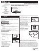
A. Fixture housing (2x2 Model Shown Below)
Alojamiento del accesorio
Boîtier de l’appareil d’éclairage
PACKAGING CONTENTS/CONTENIDO DEL PAQUETE (2 ft Model Pictured)
WARNING
2GR8432R
2GR8332
2GR8432
2GR8432L35W218G
(2x4 model)
Fig. 3
Black ring indicates
black wire placement
Fig.5
1
1
3
1
1
3
A
A
A
REMOVAL
A. Push clip towards lens
and inside the frame to
remove lens.
Access Plate
Fig.2
Fig. 1
2GR8U6T8R
(2x2 model)
Fig. 4
A
Step 1
Step 2
Leading
End
A