OPERATING INSTRUCTION MANUAL MODEL 2200P PH ANALYZER REV. 9.1 AquaMetrix Inc. 22-121 Granton Drive Richmond Hill, ON Canada, L4B 3N4 Tel: (800) 742-1413 (905) 763-8432 Fax: (905) 763-9480 www.aquametrix.
TABLE OF CONTENTS SECTION DESCRIPTION PAGE 1 GENERAL INFORMATION 1 2 SPECIFICATIONS 2 3 INSTALLATION 3 4 DESCRIPTION OF FUNCTIONS 9 5 START-UP AND OPERATION 15 6 OPERATING HINTS 22 7 UTILITY MENU 23 8 DIAGNOSTICS 26 9 TROUBLESHOOTING AND SERVICE 28
MODEL 2200P pH CONTROLLER INSTRUCTION MANUAL 1.0 GENERAL INFORMATION The AquaMetrix Model 2200P pH analyzer is a versatile industrial microprocessor based instrument. Setpoints and outputs are programmed through the menu with push buttons on the face of the instrument. Calibration is achieved from the front panel menu. The instrument may be used in conjunction with AquaMetrix 5-wire differential probes or with any conventional combination probes.
2.0 SPECIFICATIONS DISPLAY: 4 x 7 segment _” LED Display MEASURING RANGES: pH: 0.01 to 14.00 pH Temperature: 0°C to 100°C (32°F to 212°F) POWER REQUIREMENTS: Standard: 98-132 Vac, 50/60 Hz (less than 20 VA) Optional: 196-264 Vac, 50/60 Hz (less than 20 VA) 23-26Vdc (nominal current 150mA) AMBIENT CONDITIONS: -30 to 50°C (-22 to 122°F) 0 to 90% R.H.
3.0 INSTALLATION 3.1 Location 3.1.1 Install the instrument within 3000 feet of where the AquaMetrix differential probe (P60 Series) is installed. If a conventional combination probe (P500 Series) is used the instrument must be within 25 feet of the probe for direct connection. An AquaMetrix 101 Series preamplifier may be used to extend this distance to 3000 feet. 3.1.
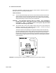
3.4 Electrical Connections The 2200P is available in 3 different power options, 120Vac, 240Vac, and 24Vdc. Refer to following sections for connecting the input power. 120Vac and 240Vac 3.4.1 To access the terminal strips open the door of the instrument and then unscrew the captive retaining screw near the upper right hand corner of the panel. Now swing open the panel to reveal the terminal strip on the power supply circuit board and the smaller terminal strip on the back of the main circuit board.
24Vdc 3.4.3 To access the terminal strips open the door of the instrument and then unscrew the captive retaining screw near the upper right hand corner of the panel. Now swing open the panel to reveal the terminal strip on the power supply circuit board and the smaller terminal strip on the back of the main circuit board. 3.4.4 The terminal strip on the power supply board at the back of the instrument is labeled for input power, relay outputs and analog outputs.
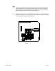
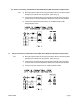
3.5 Sensor Connections 3.5.1 Jumpers J42 are used to select which type of probe is being used. If a differential probe (P60) is used, ensure that both J42 jumpers are in the up position. If a combinational probe is used, ensure that both jumpers are in the down position. (Refer to Fig. 2) 3.5 Probe Connections: DIFFERENTIAL PROBE (P60 SERIES) 3.5.1 Model 2200P Ensure that both J42 jumpers are in the up position, leaving the pins nearest to the bottom exposed.
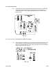
3.6 Sensor Connections; Combination Probe (P500K Series) With Temperature Compensation 3.6.1 a) Both J42 jumpers located on the swing-out board must be in the down position leaving the pin nearest to the top exposed. (Refer to Fig. 4) b) Connect the active electrode (ring terminal) to the terminal post on the swingout board and connect the shield to the SH terminal of the terminal strip TB2. c) Connect the temperature sensor wires to YL and BK terminals of TB2 disregarding the colors. 3.
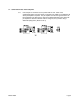
3.7 Combination Probe with Preamplifier 3.7.1 Model 2200P If the analyzer is mounted in such a position that the 10 ft. cable on the combinational probe cannot be directly connected to the 2200P. An AquaMetrix 101 Series preamplifier is required. The pre-amplifier converts the signal so that it can be transmitted up to 3000 feet, the same as the differential (P60) probe. When the pre-amplifier is used the controller must be configured, as if you were using a differential (P60) probe. (Refer to FIG.
4.0 Description of Functions 4.1 Overview 4.1.1 The Model 2200P is a microprocessor operated pH analyzer designed for industrial applications. It is compatible with a wide range of AquaMetrix pH probes and offers several measurement ranges. The software in the unit makes the instrument very easy to operate and maintain. 4.1.2 The outputs include voltage-free relay contacts and industry standard analog transmission signals. Three programmable relays are provided for process control and alarm.
4.2 Calibration 4.2.1 All pH systems need to be calibrated when first placed in service and thereafter from time to time. The frequency of calibration can only be found by the operator’s experience with each process. Calibration must always be performed when a new sensor is placed in service. 4.2.2 Calibration is accomplished by using buffer solutions, of known pH, and adjusting the instrument to show the known pH value. Buffers are available in 500 mL bottles and in 20 L packs from AquaMetrix.
4.5 Analog Outputs 4.5.1 The analog output signals consist of a non-isolated 0-1 mA, 0-5 Vdc, and isolated 420 mA signals. 4.5.2 From the factory all of the analog outputs have a linear range corresponding to the full range of the instrument. The outputs can be scaled to another linear range by entering two values: • Output High: This is the pH value at which you wish to have 100% output. • Output Low: This is the pH value at which you wish to have 0% output. 4.5.
4.6.4 When in the menu mode, the display initially shows the current value of the parameters, such as the setpoint of the control relay, while putting all of the outputs on hold. The two arrow buttons are used to adjust the display value up or down. To accept the new value press ENTER twice. While the value on the display is being changed, the relay outputs and the analog outputs remain on hold.
4.7.
4.11 Manual Override for Control Relay A 4.11.1 The AUTO/OFF/ON button is used to set the operating mode of Relay A. This useful feature allows the operator to check the operation of the device controlled by the relay. On power up the control relay always returns to the AUTO setting. Be sure to return to AUTO after completing your test if you wish to work automatically. 4.12 Utility Menu 4.12.
5.0 START-UP AND OPERATION 5.1 Password 5.1.1 To enter the menu press MENU and the PASSWORD LED will illuminate. If the dip switch has disabled the password feature, TEST will be the first menu item illuminated when the MENU button is pressed. With each press of MENU button you will step through the menu. When the last item, ALARM LOW is reached the menu wraps around to TEST. If you have enabled PASSWORD by placing DIP Switch No.
actual value, or the buffer solution is contaminated. If you are confident in your buffer solution proceed by using the arrow keys to correct the display to read the actual value of the buffer. Press ENTER. The display will flash until ENTER is pressed again to confirm the value. c) Rinse the probe in the clean water, and place it in the second buffer solution. Repeat the same process as above to accept the second value. d) The system is now calibrated.
5.4 Analog Output Range Expand 5.4.1 To increase the resolution of the analog outputs, the range may spread over any section of the scale. as long as is spans at least 10% of full scale. The best way to describe this setup is by example. Suppose you wish the outputs to span from 4 pH to 10 pH. Proceed as follows: a) Enter the menu by pressing MENU until the OUTPUT HIGH LED is illuminated. Use the arrows keys to make the display read 10.00. Press ENTER.
5.6 Control Relay A Relay Off Setpoint 5.6.1 If you have configured the relay to control decreasing pH, the relay off setpoint will be higher than the relay on setpoint. i.e. the auxiliary device connected to the relay will increase the pH. If you have configured the instrument to control increasing pH, the relay off setpoint will be lower than the relay on setpoint. i.e. the auxiliary device connected to the relay will decrease the pH.
5.9 Cycle Feature for Relays A and B 5.10.1 The 2200P has a cycling feature for the control relays. This feature if enabled will cause the relays to cycle based on the on and off times selected. This useful feature can help eliminate overshooting, saving expensive chemicals. a) If you wish to have cycling control for Relay A, you must put DIP switch NO. 3 of Bank S2 in “ON” position. Similarly, if you wish to have cycling control for Relay B, put DIP switch No. 4 of Bank S2 in “ON” position (See Section 4.
5.10 Alarm High 5.11.1 The instrument is fitted with a relay, which is set to activate on both high and low alarm conditions. The deadband is factory set. To set the ALARM HIGH proceed as follows. a) Press MENU to enter the menu, proceed by pressing MENU until the ALARM HIGH LED is illuminated. Use the arrow keys make the display read the desired value. Press ENTER. The display will flash until ENTER is pressed again to confirm the value.
5.13 Temperature 5.14.1 The temperature of the process can be read at any time by entering the menu and scrolling through the menu until TEMPERATURE LED is illuminated. Either °C or °F will be indicated depending on the position of DIP switch No.1 of Bank S1. If the temperature is suspected of being incorrect, place the S41 switch on the back of the main circuit board, in the up position, (this places a 300 ohm across the BL and YL terminals) the temperature should read 25°C or 77°F.
6.0 OPERATING HINTS 6.1 Probe Care 6.1.1 Keep the probe clean using the procedure recommended in the probe manual. Although the differential probe will continue to operate when fouled, excessive fouling may cause incorrect readings or very slow response. 6.1.2 Be sure the probe cable is well protected. The probe cable should be run in conduit but never in the same conduit with line power. Sufficient excess cable should be allowed for removal of the probe for cleaning and calibrating. 6.1.
7.0 UTILITY MENU 7.1 Utility Menu Functions 7.1.1 The Utility Menu enables authorized personnel to perform the following: • • • • • Change the range Calibrate the temperature Adjust the temperature output range Fine tuning the 0-1 mA/ 0-5 Vdc output Fine tuning the 4-20 mA output 7.2 Access to Utility Menu 7.2.1 The Utility Menu is protected by password. To access the Utility Menu press and hold both RUN and ENTER for five seconds until the PASSWORD LED illuminates. The green STATUS light will flash.
7.3 Range Change 7.3.1 The following ranges are offered for the 2200P: • • • • 7.3.2 0 to 14 pH 2 to 12 pH 0 to 10 pH 4 to 10 pH You may change the range of your instrument by making adjustments to the circuit board on the swing-out panel. The analog output limits will change automatically when you change the range. You may also wish to adjust the range expand at this time. See Section 5.4. To change the range proceed as follows: a) Enter the Utility menu as described in 7.2.1.
7.4 Temperature Calibration 7.4.1 The temperature channel was calibrated at the factory. It is a single point calibration at 25°C. If needed, this calibration can be repeated as follows: a) Disconnect the temperature sensor wires from terminals BK and YL on TB2. b) Enter the Utility Menu, as described in 7.2.1. c) Press MENU until the TEMPERATURE LED illuminates which is “Temperature calibration” in the Utility Menu. d) Place slide switch S41 in the ‘up’ (TEST) position. e) Adjust the display to read 25.
7.6 Adjust 0-1 mA / 0-5 Vdc Output 7.6.1 It may be desirable to fine tune the 0-1 mA / 0-5 Vdc output to take into account the characteristics of your particular loop. The following method involves a high and low calibration and requires the use of a digital multi-meter. (DMM). Proceed as follows ignoring the instrument display: a) Turn off the power to the instrument. Connect your DMM in parallel with the 0-5 Vdc output terminals on the power supply board. b) Turn on the power.
8.0 DIAGNOSTICS 8.1 Description 8.1.1 The 2200P has diagnostic features which alerts the operator to invalid entries and memory loss. Invalid entries are indicated by the flashing of the appropriate menu LED. The flashing will commence after RUN is pressed and will continue until the errors are corrected. Memory loss is indicated by the flashing of TEST and by the alarm relay if enabled by DIP Switch No. 5 of Bank S1. See Section 4.7.3. 8.2 Invalid Calibration 4.8.
9.0 TROUBLESHOOTING AND SERVICE 9.1 Calibration / Display Problem 9.1.1 If the problem is one of inability to calibrate or the display does not appear to match the input, try the RESET feature. See Section 6.4. In rare cases, the ESCAPE feature might be used. See Section 9.3. 9.2 Isolate the cause 9.2.1 When a measurement problem occurs, the first step is to try to isolate the cause. If the 2200P is powered, go through the menu and check your settings. A convenient way to do this is to call TEST.
9.2.5 To find out whether the problem is in the sensor, or in the analyzer, use the selftesting features. Do not disconnect the sensor. Proceed as follows: a) Move the slide switch S40, if you are using an AquaMetrix differential probe (P60 series), or S41 if you are using a conventional probe (P500 series), from position “ON LINE” to position “TEST”. Turn the pH simulation potentiometer R65 from end to end. The display should change between 0.00 and 14.00 pH.
9.3.5 After the "ESCAPE" procedure it is necessary to do the following: a) Calibrate the temperature as described in Section 7.4. b) Tune the analog outputs and the temperature output span to suit your particular application and loop. See Sections 7.5, 7.6 and 7.7. c) Leave the Utility Menu by pressing RUN. d) Calibrate the pH, as described in Section 5.2. e) Set up the user values for: • • • • • f) Output High and Low – See Section 5.4 Control Relay A – See Sections 5.5 and 5.
9.7 Parts and Accessories 9.7.1 The major parts are listed below. When ordering parts please use the complete part number. Description Part # 500 mL pH 4 Buffer Solution 500 mL pH 7 Buffer Solution 500 mL pH 10 Buffer Solution Fuse, 0.25A Quantity of 5 2200 Power Supply Circuit Board Assembly 120 Vac 2200 Power Supply Circuit Board Assembly 240 Vac 2200P Main Circuit Board Assembly (includes front panel and hinges) A35-13 A35-14 A35-24 A35-72 C13-103A C13-103B C13-2200P 9.8 Instrument Return 9.8.
STATEMENTS OF CONFORMITY FROM THE MANUFACTURER U.S.A. Canada WARNING: This equipment generates, uses, and can radiate radio frequency energy and if not installed and used in accordance with the instructions manual, may cause interference to radio communications.