OPERATING INSTRUCTION MANUAL MODEL 575 / 585 COMBINATIONAL PH AND ORP PROBES N116-27 REV. 5.0 AquaMetrix Inc. 1245 Maple Hill Court, Unit 7 Newmarket, ON Canada, L3Y 9E8 Tel: (800) 742-1413 (905) 954-0841 Fax: (905) 954-0415 www.aquametrix.
P575 AND R575 SERIES & P585 AND R585 SERIES pH AND ORP PROBES INSTRUCTION MANUAL 1.0 GENERAL INFORMATION This manual covers all AquaMetrix P/R575 and P/R585 Series conventional combination pH and ORP probes. All mounting configurations are described. Consult factory before using the sensor in extremely strong solvents such as ethylene dichloride. Before placing the sensor into operation, remove the protective plastic cap. Store this cap for future use.
2.0 SPECIFICATIONS MEASURING RANGES: pH: 0.01 to 14.00 pH ORP: -1000 to +1000 mV Consult factory for applications below 2.
3.0 INSTALLATION 3.1 General Instructions 3.1.1 Specific instructions for each type of probe are given in the following pages. Common to all probes are the following instructions: a) If the distance between the probe and the instrument is such that a direct connection is not possible you will need a preamplifier, AquaMetrix Model 101A. The box should be well sealed and away from corrosion danger. Be sure that you have sufficient slack cable to allow for probe removal for calibration and servicing.
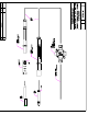
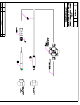
d) Route the sensor cable through an appropriate length of 1” pipe and using thread sealant, screw the pipe onto the reducer on the probe. The process should not be allowed to come in contact with the cable end of the probe. REFER TO DWG# N106-80 3.4 Flow-through tee mounting P575 and P585 3.4.1 Apply pipe sealant to the electrode end of the probe and screw it into a standard 1 1/2” NPT tee. 3.5 Flow-through tee mounting P585 and P585 3.5.1 Take the compression fitting apart.
4.2 Storage 4.2.1 Do not discard the protective cap that came with the sensor. If the sensor is removed from the process for an extended period of time, thoroughly clean the sensor, put a piece of cotton ball with few drops of water into the protective cap and replace it on the sensor. This keeps the junction from drying out which causes slow response when put back into operation or causes permanent damage to the sensor. Sensors should not be left in dry lines or empty tanks for extended periods.
N130-8 R0 Each sensor is identified with a unique serial number that is used by Aquametrix, Inc. to validate the month and year of shipment. A warranty claim will not be honored if defects are not reported within the warranty period, or if AquaMetrix determines that defects or damages are due to normal wear, misapplication, lack of maintenance, abuse, improper installation, alteration, or abnormal conditions.