SHARKTX & SHARKTXP MULTI-PARAMETER TRANSMITTER USER’S MANUAL Rev 2 AquaMetrix Inc. 1245 Maple Hill Ct., Unit 7 Newmarket, ON Canada, L3Y 9E8 Tel: (800) 742-1413 (905) 954-0841 Fax: (905) 954-0415 www.aquametrix.
MULTI-PARAMETER TRANSMITTER USER’S MANUAL Table of Contents Subject Page No.
MULTI-PARAMETER TRANSMITTER USER’S MANUAL Introduction The SHARKTX & SHARKTXP multi-parameter transmitter is a microprocessor based transmitter capable of measuring one of the following parameters, pH, ORP, conductivity or flow. When shipped from the factory, the Shark is not set to measure any one parameter. When the Shark is powered up for the first time, it will display the meter selection screen where the meter type must be selected. (refer to section 4.
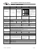
MULTI-PARAMETER TRANSMITTER USER’S MANUAL Section I - Specifications Display Power Requirements Measuring Range Temperature Compensation Temperature Unit Temperature Sensor Calibration Modes Ambient Conditions Sensor to Transmitter Distance Analog Output Memory Back-up Mechanical Sensor Input Invalid Entries Manual Test Mode Output Hold Calibration Data Auto Return Display Damping Net Weight Approvals pH ORP 2 x 16 alpha-numeric LCD display 4 to 20mA, Loop Powered, 16 to 32 VDC Conductivity Flow
MULTI-PARAMETER TRANSMITTER USER’S MANUAL Section 2 - Installation 2.1 Unpacking Save the shipping carton and packing material in case the instrument needs to be stored or returned. Inspect the instrument and packing material for shipping damage and report any problems immediately. 2.2 Location Locate the transmitter close to the sensor. The list below gives typical maximum distances for various sensors. Refer to the sensor specifications for exact information.
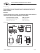
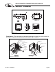
MULTI-PARAMETER TRANSMITTER USER’S MANUAL Section 2 - Installation Fig 2.2 SHARKTXP Transmitter dimensions Dwg# N106-129 Panel Mount – The transmitters can be panel mounted to a panel using the hardware kit provided. The panel cutout dimensions are shown in fig. 2.1 and 2.2. Figure 2.3 Panel Mount EXTERNAL PANEL GASKET QTY.1 PANEL (CUSTOMER SUPPLIED) UNIVERSAL MOUNTIN G BRACKET QTY.1 SCREW 10-24 X 1/2" QTY.4 UNIVERSAL MOUNTING CLAMP QTY.2 SCREW 1/4-20 X 2-1/2" QTY.4 EXTERNAL PANEL GASKET QTY.
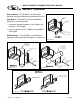
MULTI-PARAMETER TRANSMITTER USER’S MANUAL Section 2 - Installation Surface Mount – The SHARKTX can be surface mounted using the hardware kit provided with the unit. Figure 2.4 Surface Mount UNIVERSAL MOUN TING BRACKET QTY.1 Pipe Mount – The SHARKTX can be mounted to a horizontal or vertical pipe with: SCREW 10-24 X 1/2" QTY.4 • a minimum outside diameter of 1.30” (33mm) (for example 1” CPVC pipe) • and a maximum of 2.375” (60mm) (for example 2” CPVC pipe) HOLES Ø1/4" FOR MOUNTING SCREWS QTY.
MULTI-PARAMETER TRANSMITTER USER’S MANUAL Section 3 - Electrical Connections and Setup 3.1 Conduit Connections The SHARKTX has two 1/2” conduit holes at the bottom of the enclosure as shown on fig. 2.1. The unit is shipped with these holes plugged with liquid tight conduit seals. These must be left in unused holes to maintain the NEMA 4X integrity. Use approved conduit hubs to connect the conduit, connect these to the conduit before connecting to the enclosure. 3.2 Power Connections Figure 3.
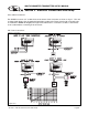
MULTI-PARAMETER TRANSMITTER USER’S MANUAL Section 3 - Electrical Connections and Setup 3.3 pH and ORP Differential Probe connections and setup The drawing shows the connections for the Aquametrix Differential (5 wire) probe. The cable should be run in a conduit separate from AC power wires, and via a separate conduit hole. Figure 3.2 Connections for Differential (5 wire) pH or ORP probe Dwg# N104-42 Once connected, step through the LCD menus to select the probe in the order shown.
MULTI-PARAMETER TRANSMITTER USER’S MANUAL Section 3 - Electrical Connections and Setup 3.4 pH or ORP Combination Probe connections and setup The drawing shows the connections for the Aquametrix Combination probe. The cable should be run in a conduit separate from AC power wires, and via a separate conduit hole. The cable length should not exceed 10 feet (3 meters). The 2 wire version has no temperature sensor and is connected via a coaxial wire.
MULTI-PARAMETER TRANSMITTER USER’S MANUAL Section 3 - Electrical Connections and Setup 3.5 Conductivity Cell (Contacting style) connections and setup The drawing shows the connections for the Aquametrix Conductivity Cells (Contacting style). The cable should be run in a conduit seperate from the AC power wires, and via a seperate conduit hole. The cell cable length should not exceed 300ft. (91 meters). Figure 3.
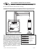
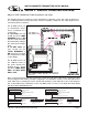
MULTI-PARAMETER TRANSMITTER USER’S MANUAL Section 3 - Electrical Connections and Setup 3.6 Paddle Wheel Flow Sensor connections and setup The drawing shows the connnections for a typical paddle wheel flow sensor. The cable to the sensor should not exceed 2000’ (600 meters). Figure 3.5 Connections for Flow Sensor Dwg# N104-45 Once connected, step through the LCD menus to select the sensor in the order shown. The Sensor K factor (pulses per U.S.
MULTI-PARAMETER TRANSMITTER USER’S MANUAL Section 3 - Electrical Connections and Setup 3.10 MANUAL TEST MODE (LCD MENU SECTIONS - pH: 4.4, ORP: 5.3, Conductivity: 6.4, Flow: 7.2) The setup can be tested using Manual Test Mode to simulate process changes. MANUAL TEST MODE is used to simulate a process reading in order to verify the correct response of the output. 3.11 4-20 mA Isolated Output (LCD MENU SECTIONS - pH: 4.15, ORP: 5.14, Conductivity: 6.16, Flow: 7.
MULTI-PARAMETER TRANSMITTER USER’S MANUAL Section 4 - Using the Transmitter in pH Mode 1/4" TURN SCREWS (FOR SHARKTX ONLY) 2 LINE, 16 CHARACTER LCD DISPLAY MAIN MENU INTERFACE SCREEN UNIT LABEL LABEL TO INDICATE UNIT OF MEASURE SHARK IS CONFIGURED FOR. SIMPLE THREE-BUTTON INTERFACE FOR FAST & EASY SETUP (REFER TO SECTIONS 4.0 TO 4.
MULTI-PARAMETER TRANSMITTER USER’S MANUAL pH - Menu Overview 4.0 RUN MODE 7.15pH 25.0C DOWN CALIBRATION DOWN MANUAL CAL pH UTILITIES DOWN DOWN AUTO CAL pH SETUP DOWN DOWN TEMP CALIBRATION DIAGNOSTICS DOWN DOWN MANUAL CALIBRATE pH PROBE SEC. 4.1 AUTO CALIBRATE pH PROBE SEC. 4.2 CALIBRATE TEMP. SENSOR IN pH PROBE SEC. 4.3 EXIT OUTPUT DOWN DOWN EXIT DOWN PROBE SELECT DOWN TEMP UNIT MANUAL TEST MODE SELECT TYPE OF pH PROBE SEC. 4.6 SELECT DEG C OR DEG F SEC 4.
MULTI-PARAMETER TRANSMITTER USER’S MANUAL pH - Calibration Menu - Manual Calibrate 4.1 7.15pH 25.0C RUN MODE DOWN CALIBRATION MANUAL CAL pH Place the probe in the first buffer solution, be sure to clean and rinse the Probe first with D.I. water and then insert it in the 7.00 buffer. IF BUFFER1 READY PRESS 'DOWN' Press DOWN RUNNING MANU CAL BUFFER1 WAIT... MANUAL CAL pH BUFFER1 UP 7.3 5 > DOWN MANUAL CAL pH BUFFER1 7.0 0 > MANUAL CAL pH BUFFER1 7.
MULTI-PARAMETER TRANSMITTER USER’S MANUAL pH - Calibration Menu - Auto Calibrate 4.2 7.15pH 25.0C RUN MODE DOWN CALIBRATION MANUAL CAL pH DOWN AUTO CAL pH Place the probe in the first buffer solution, be sure to clean and rinse the Probe first with D.I. water and then insert it in the 7.00 buffer. IF BUFFER1 READY PRESS 'DOWN' DOWN Press RUNNING AUTO CAL BUFFER1 WAIT... If an erros occurs, the controller will indicate a "BUFFER ERROR" alarm.
MULTI-PARAMETER TRANSMITTER USER’S MANUAL pH - Calibration Menu - Temperature Calibration 4.3 7.15pH 25.0C RUN MODE DOWN CALIBRATION MANUAL CAL pH If the Temperature Compensation Override is set to ON (see section 4.11), the Shark cannot calibrate the temperature sensor. This display will appear to alert the user to the condition. DOWN AUTO CAL pH DOWN TEMP CALIBRATION TEMP CALIBRATION TEMP O/R ON > DOWN The controller displays the current probe temperature.
MULTI-PARAMETER TRANSMITTER USER’S MANUAL pH - Utilities Menu - Manual Test Mode 4.4 7.15pH 25.0C Manual Test Mode is used to simulate a process reading in order to verify the correct response of the output. When in the Manual Test Mode, the output IS no longer placed on hold as it is when in the rest of the menu. RUN MODE DOWN CALIBRATION DOWN UTILITIES MANUAL TEST MODE TEST 7.00 > 12.0mA Press the key once which will move the cursor over the least digit of the simulated process value.
MULTI-PARAMETER TRANSMITTER USER’S MANUAL pH - Utilities Menu - Meter Selection 4.5 7.15pH 25.0C RUN MODE The Meter Selection menu is used to select the meter type that the controller is configured for, either pH, ORP, Conductivity or FLow. Once selected, the controller will initialize itself for the selected meter's functionality and move to run mode. DOWN CALIBRATION DOWN UTILITIES MANUAL TEST MODE Press the key to initialize the controller as a pH meter.
MULTI-PARAMETER TRANSMITTER USER’S MANUAL pH - Setup Menu - Probe Select 4.6 7.15pH 25.0C RUN MODE DOWN CALIBRATION DOWN PROBE SELECT will allow the user to select whether the probe is a 2 or 4 wire combination probe, or a 5 wire differential probe. UTILITIES DOWN SETUP PROBE SELECT PROBE SELECT DIFFERENTIAL > DOWN Use the UP or DOWN keys to scroll through the probe types available.
MULTI-PARAMETER TRANSMITTER USER’S MANUAL pH - Setup Menu -Temp Unit 4.7 7.15pH 25.0C RUN MODE TEMP UNIT allows the user to select either Degrees Centigrade or Fahrenheit units for display DOWN CALIBRATION DOWN UTILITIES DOWN SETUP PROBE SELECT DOWN TEMP UNIT TEMP UNIT DEGREE C > TEMP UNIT DEGREE C UP Press the key once which will move the cursor over the unit type, C or F.
MULTI-PARAMETER TRANSMITTER USER’S MANUAL pH - Setup Menu - Temp. Sensor 4.8 7.15pH 25.0C RUN MODE TEMP SENSOR allows the user to select the type of temperature sensor used the in the probe. DOWN CALIBRATION The factory default for pH is a 300 Ω NTC Thermistor. The user can also select a 3000 Ω NTC Thermistor or a 1000 RTD. DOWN UTILITIES DOWN SETUP PROBE SELECT DOWN TEMP UNIT TEMP SENSOR TEMP SENSOR 300 Ω NTC > Press the key once which will move the cursor over to the sensor type.
MULTI-PARAMETER TRANSMITTER USER’S MANUAL pH - Setup Menu - Auto Return 4.9 7.15pH 25.0C RUN MODE AUTO RETURN is used to select what conditions will cause the controller to time-out of the operations menu DOWN CALIBRATION DOWN UTILITIES DOWN SETUP MENU ON will cause the controller to exit the menu and revert back to the online run mode after 10 minutes with no buttons pressed. This feature ensures that if a user forgets to return back to run mode, the controller will not be left in an offline state.
MULTI-PARAMETER TRANSMITTER USER’S MANUAL pH - Setup Menu - T.Comp Override 4.10 7.15pH 25.0C RUN MODE Temperature Compensation Override is used to manually set the actual probe or process temperature. This is useful if the probe does not have a temperature sensor or if the process temperature is constant. When the override is enabled, the controller will use the selected temperature when performing temperature compensation calculations.
MULTI-PARAMETER TRANSMITTER USER’S MANUAL pH - Setup Menu - Display Damping 4.11 7.15pH 25.0C RUN MODE DOWN CALIBRATION DOWN UTILITIES The Display Damping menu allows the user to adjust the rate at which the display and the output is updated. This allows the user to dampen out unstable process readings. The damping can be set from 0 seconds to 10 seconds. (default value is 0 sec.) DOWN SETUP PROBE SELECTION DOWN TEMP UNIT DOWN TEMP SENSOR DOWN AUTO RETURN DOWN T.
MULTI-PARAMETER TRANSMITTER USER’S MANUAL pH - Diagnostics Menu - Firmware Rev 4.12 7.15pH 25.0C RUN MODE DOWN CALIBRATION The FIRMWARE REV menu allows the user to see what revision of the firmware is currently installed in the controller. This is a Read Only menu item. DOWN UTILITIES DOWN SETUP DOWN DIAGNOSTICS FIRMWARE REV. FIRMWARE REV. 1.00 DOWN pH - Diagnostics Menu - Firmware Rev 4.
MULTI-PARAMETER TRANSMITTER USER’S MANUAL pH - Diagnostics Menu - Calibration Data 4.13 7.15pH 25.0C RUN MODE The Calibration Data menu is a series of read only screens which allow the user to view the data collected during the last calibration. DOWN CALIBRATION DOWN UTILITIES DOWN SETUP DOWN DIAGNOSTICS FIRMWARE REV. DOWN CALIBRATION DATA Press to view the first Calibration Data screen. CALIBRATION DATA MODE 2PT > Press DOWN to view the next Calibration Data screen.
MULTI-PARAMETER TRANSMITTER USER’S MANUAL pH - Diagnostics Menu - Sensor Input 4.14 7.15pH 25.0C RUN MODE DOWN CALIBRATION DOWN The Sensor Input Menu allows the user to view real time, uncompensated process data from the probe. This is a Read only menu item. UTILITIES DOWN SETUP DOWN DIAGNOSTICS FIRMWARE REV. DOWN CALIBRATION DATA DOWN SENSOR INPUT Press to view the Sensor Input data.
MULTI-PARAMETER TRANSMITTER USER’S MANUAL pH - Output Menu - 4-20mA Output 4.15 RUN MODE 7.15pH 25.0C The Transmitter has a single 4-20mA output, electrically isolated from the ground. The output can source current into a maximum of 800 ohms. See Section 3.9 for wiring diagram. The channel has a fully adjustable 4 & 20 mA output adjustments. This will enable the operator to span the output over the desired range.
MULTI-PARAMETER TRANSMITTER USER’S MANUAL Section 5 - Using the Transmitter in ORP Mode 1/4" TURN SCREWS (FOR SHARKTX ONLY) 2 LINE, 16 CHARACTER LCD DISPLAY MAIN MENU INTERFACE SCREEN UNIT LABEL LABEL TO INDICATE UNIT OF MEASURE SHARK IS CONFIGURED FOR. SIMPLE THREE-BUTTON INTERFACE FOR FAST & EASY SETUP (REFER TO SECTIONS 5.0 TO 5.
MULTI-PARAMETER TRANSMITTER USER’S MANUAL ORP - Menu Overview 5.0 RUN MODE 500mV 25.0C DOWN CALIBRATION DOWN MANUAL CALIBRATE ORP PROBE SEC. 5.1 MANUAL CAL ORP UTILITIES DOWN DOWN TEMP CALIBRATION DOWN EXIT SETUP DOWN DIAGNOSTICS CALIBRATE TEMP. SENSOR IN ORP PROBE SEC. 5.2 DOWN DOWN OUTPUT DOWN MANUAL TEST MODE EXIT DOWN DOWN PROBE SELECT DOWN TEMP UNIT SELECT TYPE OF ORP PROBE SEC. 5.5 SELECT DEG C OR DEG F SEC 5.6 DOWN AUTO RETURN DOWN T.
MULTI-PARAMETER TRANSMITTER USER’S MANUAL ORP - Calibration Menu - Manual Calibrate 5.1 500mV 25.0C RUN MODE DOWN CALIBRATION MANUAL CAL ORP Place the probe in the buffer solution, be sure to clean and rinse the Probe first with D.I. water and then insert it in the mV buffer. IF BUFFER READY PRESS ©DOWN© Press DOWN DOWN The controller will read the mV value, averaging a number of results to get a stable calibration value. RUNNING MANU CAL BUFFER WAIT...
MULTI-PARAMETER TRANSMITTER USER’S MANUAL ORP - Calibration Menu - Temp. Calibration 5.2 500mV 25.0C RUN MODE If the Temperature Display Override is set to ON (see section 5.10), the Shark cannot calibrate the temperature sensor. This display will appear to alert the user to the condition. DOWN CALIBRATION MANUAL CAL ORP DOWN TEMP CALIBRATION TEMP CALIBRATION TEMP O/R ON > DOWN The controller displays the current probe temperature. If this incorrect, the controller can be adjusted to compensate.
MULTI-PARAMETER TRANSMITTER USER’S MANUAL ORP - Utilities Menu - Manual Test Mode 5.3 500mV 25.0C Manual Test Mode is used to simulate a process reading in order to verify the correct response of the output. When in the Manual Test Mode, the outputs is no longer placed on hold as it is when in the rest of the menu. RUN MODE DOWN The range is 0 to +1000mV. CALIBRATION DOWN UTILITIES MANUAL TEST MODE TEST 500 > 12.
MULTI-PARAMETER TRANSMITTER USER’S MANUAL ORP - Utilities Menu - Meter Selection 5.4 500mV 25.0C The Meter Selection menu is used to select the meter type that the controller is configured for, either pH, ORP, Conductivity or FLow. Once selected, the controller will initialize itself for the selected meter's functionality and move to run mode. RUN MODE DOWN CALIBRATION DOWN UTILITIES MANUAL TEST MODE Press the key to initialize the controller as a pH meter.
MULTI-PARAMETER TRANSMITTER USER’S MANUAL ORP - Setup Menu - Probe Select 5.5 500mV 25.0C RUN MODE DOWN CALIBRATION DOWN PROBE SELECT will allow the user to select whether the probe is a 2 or 4 wire combination probe, or a 5 wire differential probe. UTILITIES DOWN SETUP PROBE SELECT PROBE SELECT DIFFERENTIAL > DOWN Use the UP or DOWN keys to scroll through the probe styles available.
MULTI-PARAMETER TRANSMITTER USER’S MANUAL ORP - Setup Menu - Temp. Unit 5.6 500mV 25.0C RUN MODE TEMP UNIT allows the user to select either Degrees Centigrade or Fahrenheit units for display DOWN CALIBRATION DOWN UTILITIES DOWN SETUP PROBE SELECT DOWN TEMP UNIT TEMP UNIT DEGREE C > TEMP UNIT DEGREE C UP Press the key once which will move the cursor over the unit type, C or F.
MULTI-PARAMETER TRANSMITTER USER’S MANUAL ORP - Setup Menu - Temp. Sensor 5.7 500mV 25.0C RUN MODE TEMP SENSOR allows the user to select the type of temperature sensor used in the probe. DOWN CALIBRATION The factory default for ORP is a 300 NTC Thermistor. The user can also select a 3000 NTC Thermistor or a 1000 RTD. DOWN UTILITIES DOWN SETUP PROBE SELECT DOWN TEMP UNIT TEMP SENSOR TEMP SENSOR 300 NTC > Press the key once which will move the cursor over to the sensor type.
MULTI-PARAMETER TRANSMITTER USER’S MANUAL ORP - Setup Menu - Auto Return 5.8 500mV 25.0C RUN MODE DOWN AUTO RETURN is used to select what conditions will cause the controller to time-out of the operations menu CALIBRATION DOWN UTILITIES DOWN SETUP MENU ON will cause the controller to exit the menu and revert back to the online run mode after 10 minutes with no buttons pressed. This feature ensures that if a user forgets to return back to run mode, the controller will not be left in an offline state.
MULTI-PARAMETER TRANSMITTER USER’S MANUAL ORP - Setup Menu - Temp. Display Override 5.9 500mV 25.0C RUN MODE T. Display Override is used to blank the Temperature Display on the LCD menu and place 4 dots on the LED menu when Temp display is requested.This is to ensure the user isn't shown a temperature value that isn't valid.
MULTI-PARAMETER TRANSMITTER USER’S MANUAL ORP - Setup Menu - Display Damping 5.10 500mV 25.0C RUN MODE DOWN CALIBRATION DOWN UTILITIES The Display Damping menu allows the user to adjust the rate at which the display and the output is updated. This allows the user to dampen out unstable process readings. The damping can be set from 0 seconds to 10 seconds. (default value is 0 sec.) DOWN SETUP PROBE SELECTION DOWN TEMP UNIT DOWN TEMP SENSOR DOWN AUTO RETURN DOWN T.
MULTI-PARAMETER TRANSMITTER USER’S MANUAL ORP - Diagnostics Menu - Firmware Rev 5.11 500mV 25.0C RUN MODE DOWN CALIBRATION The FIRMWARE REV menu allows the user to see what revision of the firmware is currently installed in the controller. This is a Read Only menu item. DOWN UTILITIES DOWN SETUP DOWN DIAGNOSTICS FIRMWARE REV. FIRMWARE REV. 1.00 DOWN ORP - Diagnostics Menu - Firmware Rev 5.
MULTI-PARAMETER TRANSMITTER USER’S MANUAL ORP - Diagnostics Menu - Calibration Data 5.12 500mV 25.0C RUN MODE The Calibration Data menu is a series of read only screens which allow the user to view the data collected during the last calibration. DOWN CALIBRATION DOWN UTILITIES DOWN SETUP DOWN DIAGNOSTICS FIRMWARE REV. DOWN CALIBRATION DATA Press to view the first Calibration Data screen. CALIBRATION DATA MODE 1PT > Press DOWN to view the next Calibration Data screen.
MULTI-PARAMETER TRANSMITTER USER’S MANUAL ORP - Diagnostics Menu - Sensor Input 5.13 500mV 25.0C RUN MODE DOWN CALIBRATION DOWN The Sensor Input Menu allows the user to view real time, uncompensated process data from the probe. This is a Read only menu item. UTILITIES DOWN SETUP DOWN DIAGNOSTICS FIRMWARE REV. DOWN CALIBRATION DATA DOWN SENSOR INPUT Press to view the Sensor Input data.
MULTI-PARAMETER TRANSMITTER USER’S MANUAL ORP - Output Menu - 4-20mA Output 5.14 RUN MODE 500mV 25.0C The Transmitter has a single 4-20mA output, electrically isolated from the ground. The output can source current into a maximum of 800 ohms. See Section 3.9 for wiring diagram. The channel has a fully adjustable 4 & 20 mA output adjustments. This will enable the operator to span the output over the desired range.
MULTI-PARAMETER TRANSMITTER USER’S MANUAL Section 6 - Using the Transmitter in Conductivity Mode 1/4" TURN SCREWS (FOR SHARKTX ONLY) 2 LINE, 16 CHARACTER LCD DISPLAY MAIN MENU INTERFACE SCREEN UNIT LABEL LABEL TO INDICATE UNIT OF MEASURE SHARK IS CONFIGURED FOR. SIMPLE THREE-BUTTON INTERFACE FOR FAST & EASY SETUP (REFER TO SECTIONS 6.0 TO 6.
MULTI-PARAMETER TRANSMITTER USER’S MANUAL Conductivity - Menu Overview 6.0 RUN MODE 1000uS 25.0C DOWN CALIBRATION DOWN MANUAL CAL COND UTILITIES DOWN DOWN DRY CAL COND DOWN TEMP CALIBRATION SETUP DOWN DIAGNOSTICS DOWN DOWN CALIBRATE PROBE WITH BUFFER SOL'N SEC. 6.1 CALIBRATE PROBE WITH MANUFACTURER'S DATA SEC. 6.2 CALIBRATE TEMP. SENSOR IN PROBE SEC. 6.3 EXIT OUTPUT DOWN DOWN EXIT COND. RANGE DOWN DOWN TEMP UNIT SELECT MEASURING RANGE SEC. 6.
MULTI-PARAMETER TRANSMITTER USER’S MANUAL Conductivity - Calibration Menu - Manual Calibrate 6.1 Manual Calibration is used to "wet calibrate the cell". This can be done with the cell installed in the process, or with the cell suspended in a known buffer solution. When calibrated "In Process", the actual conductivity is determined with a grab sample or a hand held meter, and the value entered in the display.
MULTI-PARAMETER TRANSMITTER USER’S MANUAL Conductivity - Calibration Menu - Dry Cal Cond 6.2 1000uS 25.0C Dry Calibration eliminates the need for conductivity reference solutions, the user inputs the Cell K factor supplied by the factory. RUN MODE DOWN CALIBRATION MANUAL CAL COND If the conductivity cell has a tag attached to it, specifying the exact cell constant, the user is prompted to enter this value.
MULTI-PARAMETER TRANSMITTER USER’S MANUAL Conductivity - Calibration Menu - Temp. Calibration 6.3 Temperature Calibration In most cases, the factory temperature calibration is accurate enough to ensure correct temperature readings.
MULTI-PARAMETER TRANSMITTER USER’S MANUAL Conductivity - Utilities Menu - Manual Test Mode 6.4 1000uS 25.0C Manual Test Mode is used to simulate a process reading in order to verify the correct response of the output. When in the Manual Test Mode, the output is no longer placed on hold as it is when in the rest of the menu. RUN MODE DOWN CALIBRATION DOWN UTILITIES MANUAL TEST MODE TEST 1000 > 12.0mA DOWN TEST 100 0 > 12.
MULTI-PARAMETER TRANSMITTER USER’S MANUAL Conductivity - Utilities Menu - Meter Selection 6.5 1000uS 25.0C RUN MODE The Meter Selection menu is used to select the meter type that the controller is configured for, either pH, ORP, Conductivity or Flow. Once selected, the controller will initialize itself for the selected meter's functionality and move to run mode. DOWN CALIBRATION DOWN UTILITIES Press the key to initialize the controller as a pH meter.
MULTI-PARAMETER TRANSMITTER USER’S MANUAL Conductivity - Setup Menu - Conductivity Range 6.6 1000uS 25.0C RUN MODE DOWN CALIBRATION DOWN UTILITIES DOWN SETUP COND. RANGE Conductivity Range will allow the user to select the measuring range of the instrument. The ranges can be selected from any of the following: 200 mS/cm - cell constant 50 20 mS/cm - cell constant 10 5000 uS/cm - cell constant 1 200 uS/cm - cell constant 0.1 20 uS/cm - cell constant 0.1 2 uS/cm - cell constant 0.
MULTI-PARAMETER TRANSMITTER USER’S MANUAL Conductivity - Setup Menu - Temp. Unit 6.7 1000uS 25.0C RUN MODE TEMP UNIT allows the user to select either Degrees Centigrade or Fahrenheit units for display DOWN CALIBRATION DOWN UTILITIES DOWN SETUP COND RANGE DOWN TEMP UNIT TEMP UNIT DEG C > TEMP UNIT DEG C Press the key once which will move the cursor over the unit type, C or F.
MULTI-PARAMETER TRANSMITTER USER’S MANUAL Conductivity - Setup Menu - Temp. Sensor 6.8 1000uS 25.0C RUN MODE TEMP SENSOR allows the user to select the type of temperature sensor used the in the probe. The factory default for Conductivity is a 3000 Ω NTC thermistor. The user can also select a 300 Ω NTC thermistor or a Pt. 1000 RTD.
MULTI-PARAMETER TRANSMITTER USER’S MANUAL Conductivity - Setup Menu - Auto Return 6.9 1000uS 25.0C RUN MODE AUTO RETURN is used to select what conditions will cause the controller to time-out of the operations menu DOWN CALIBRATION DOWN UTILITIES MENU ON will cause the controller to exit the menu and revert back to the online run mode after 10 minutes with no buttons pressed. This feature ensures that if a user forgets to return back to run mode, the controller will not be left in an offline state.
MULTI-PARAMETER TRANSMITTER USER’S MANUAL Conductivity - Setup Menu - T. Comp Override 6.10 1000uS 25.0C RUN MODE Temperature Compensation Override is used to manually set the actual probe or process temperature. This is useful if the probe does not have a temperature sensor or if the process temperature is constant. When the override is enabled, the controller will use the selected temperature when performing temperature compensation calculations.
MULTI-PARAMETER TRANSMITTER USER’S MANUAL Conductivity - Setup Menu - Display Damping 6.11 1000uS 25.0C RUN MODE DOWN CALIBRATION DOWN UTILITIES The Display Damping menu allows the user to adjust the rate at which the display and the output is updated. This allows the user to dampen out unstable process readings. The damping can be set from 0 seconds to 10 seconds. (default value is 0 sec.
MULTI-PARAMETER TRANSMITTER USER’S MANUAL Conductivity - Setup Menu - Temp. Comp. Curve 6.12 1000uS 25.0C The Temperature Compensation Curve setting allows the user to select the temperature compensation to match a specific process. The variation of Conductivity versus Temperature is dependent on the type of solids and liquids in water, so no fixed compensation value will accurately compensate every process. This setting allows the user to fine tune the compensation to their specific process.
MULTI-PARAMETER TRANSMITTER USER’S MANUAL Conductivity - Diagnostics Menu - Firmware Rev. 6.13 1000uS 25.0C RUN MODE DOWN The FIRMWARE REV menu allows the user to see what revision of the firmware is currently installed in the controller. This is a Read Only menu item. CALIBRATION DOWN UTILITIES DOWN SETUP DOWN DIAGNOSTICS FIRMWARE REV. FIRMWARE REV. 1.00 DOWN Conductivity - Diagnostics Menu - Firmware Rev. 6.
MULTI-PARAMETER TRANSMITTER USER’S MANUAL Conductivity - Diagnostics Menu - Calibration Data 6.14 1000uS 25.0C RUN MODE The Calibration Data menu is a series of read only screens which allow the user to view the data collected during the last calibration. DOWN CALIBRATION DOWN UTILITIES DOWN SETUP DOWN DIAGNOSTICS FIRMWARE REV. DOWN Press to view the first Calibration Data screen.
MULTI-PARAMETER TRANSMITTER USER’S MANUAL Conductivity - Diagnostics Menu - Sensor Input 6.15 1000uS 25.0C RUN MODE DOWN CALIBRATION DOWN The Sensor Input Menu allows the user to view real time, uncompensated process data from the conductivity cell. This is a Read only menu item. This "Live Data" screen is useful for trouble shooting purposes when diagnosing cell or process problems. UTILITIES DOWN SETUP DOWN DIAGNOSTICS FIRMWARE REV.
MULTI-PARAMETER TRANSMITTER USER’S MANUAL Conductivity - Output Menu - 4-20mA Output 6.16 RUN MODE 1000uS 25.0C The Transmitter has a single 4-20mA output, electrically isolated from the ground. The output can source current into a maximum of 800 ohms. See Section 3.9 for wiring diagram. The channel has a fully adjustable 4 & 20 mA output adjustments. This will enable the operator to span the output over the desired range.
MULTI-PARAMETER TRANSMITTER USER’S MANUAL Section 7 - Using the Transmitter in Flow Mode 1/4" TURN SCREWS (FOR SHARKTX ONLY) 2 LINE, 16 CHARACTER LCD DISPLAY MAIN MENU INTERFACE SCREEN UNIT LABEL LABEL TO INDICATE UNIT OF MEASURE SHARK IS CONFIGURED FOR. SIMPLE THREE-BUTTON INTERFACE FOR FAST & EASY SETUP (REFER TO SECTIONS 7.0 TO 7.
MULTI-PARAMETER TRANSMITTER USER’S MANUAL Flow - Menu Overview 7.0 RUN MODE TOTAL 0 DOWN CALIBRATION DOWN K FACTOR UTILITIES DOWN DOWN ENTER FLOW SENSOR CALIBRATION FACTOR SEC. 7.1 EXIT SETUP DOWN DOWN DIAGNOSTICS DOWN OUTPUT MANUAL TEST MODE DOWN DOWN EXIT METER SELECTION DOWN DOWN UNITS OF VOLUME DOWN UNITS OF TIME DOWN AUTO RETURN DOWN DISPLAY DAMPING DOWN TOTALIZER RESET DOWN SETUP OF UNITS OF VOLUME SEC. 7.4 SETUP OF UNITS OF TIME SEC. 7.5 ENABLE TIME OUT FROM MENU SEC. 7.
MULTI-PARAMETER TRANSMITTER USER’S MANUAL Flow - Calibration Menu - K Factor 7.1 The K Factor menu is used to enter the flow sensor calibration factor. The K Factor represents the number of pulses per U.S. Gallon, generated by the combination of sensor and flow fitting. It is normally stamped on the flow fitting or attached to a tag on the cable. Typical K factors range between 0.5000 to 1500.0.
MULTI-PARAMETER TRANSMITTER USER’S MANUAL Flow - Utilities Menu - Manual Test Mode 7.2 TOTAL 0 Manual Test Mode is used to simulate a process reading in order to verify the correct response of the output. When in the Manual Test Mode, the output is no longer placed on hold as it is when in the rest of the menu. RUN MODE DOWN CALIBRATION DOWN UTILITIES MANUAL TEST MODE TEST 50.00 GPM > 12.0mA DOWN TEST 50.0 0 GPM > 12.
MULTI-PARAMETER TRANSMITTER USER’S MANUAL Flow - Utilities Menu - Meter Selection 7.3 TOTAL 0 RUN MODE The Meter Selection menu is used to select the meter type that the controller is configured for, either pH, ORP, Conductivity or FLow. Once selected, the controller will initialize itself for the selected meter's functionality and move to run mode. DOWN CALIBRATION DOWN UTILITIES MANUAL TEST MODE Press the key to initialize the controller as a pH meter.
MULTI-PARAMETER TRANSMITTER USER’S MANUAL Flow - Setup Menu - Units of Volume 7.4 The Units of Measurement is broken into two variables, UNITS OF VOLUME and UNITS OF TIME. The two variables are then combined to display the desired units of measure. For example, if units of Volume is to set Cubic Meters (CM) and Units of Time is set for Seconds (S), the controller will display flow as Cubic Meters per Second on the front LED display.
MULTI-PARAMETER TRANSMITTER USER’S MANUAL Flow - Setup Menu - Units of Time 7.5 TOTAL 0 DOWN CALIBRATION DOWN UTILITIES RUN MODE The Units of Measurement is broken into two variables, UNITS OF VOLUME and UNITS OF TIME. The two variables are then combined to display the desired units of measure. For example, if units of Volume is to set Cubic Meters (CM) and Units of Time is set for Seconds (S), the controller will display flow as Cubic Meters per Second on the front LED display.
MULTI-PARAMETER TRANSMITTER USER’S MANUAL Flow - Setup Menu - Auto Return 7.6 TOTAL 0 RUN MODE AUTO RETURN is used to select what conditions will cause the controller to time-out of the operations menu DOWN CALIBRATION DOWN MENU ON will cause the controller to exit the menu and revert back to the online run mode after 10 minutes with no buttons pressed. This feature ensures that if a user forgets to return back to run mode, the controller will not be left in an offline state.
MULTI-PARAMETER TRANSMITTER USER’S MANUAL Flow - Setup Menu - Display Damping 7.7 TOTAL 0 RUN MODE DOWN CALIBRATION DOWN UTILITIES The Display Damping menu allows the user to adjust the rate at which the display and the output is updated. This allows the user to dampen out unstable process readings. The damping can be set from 0 seconds to 10 seconds. (default value is 0 sec.
MULTI-PARAMETER TRANSMITTER USER’S MANUAL Flow - Setup Menu - Totalizer Reset 7.8 TOTAL 0 RUN MODE Totalizer Reset is used to reset the Flow totalizer to zero. DOWN Note that once complete, this action cannot be reversed. The accumulated total will be erased permanently.
MULTI-PARAMETER TRANSMITTER USER’S MANUAL Flow - Diagnostics Menu - Firmware Rev 7.9 TOTAL 0 RUN MODE DOWN CALIBRATION The FIRMWARE REV menu allows the user to see what revision of the firmware is currently installed in the controller. This is a Read Only menu item. DOWN UTILITIES DOWN SETUP DOWN DIAGNOSTICS FIRMWARE REV. FIRMWARE REV. 1.00 > DOWN NOTE PRESS THE UP AND DOWN KEYS TOGETHER TO GO IMMEDIATELY BACK TO RUN MODE Flow - Diagnostics Menu - Firmware Rev 7.
MULTI-PARAMETER TRANSMITTER USER’S MANUAL Flow - Diagnostics Menu - Calibration Data 7.10 TOTAL 0 RUN MODE The Calibration Data menu is a read only screen which allow the user to view the K factor entered during the last calibration. DOWN CALIBRATION DOWN UTILITIES DOWN SETUP DOWN DIAGNOSTICS FIRMWARE REV. DOWN CALIBRATION DATA Press to view the first Calibration Data screen. CALIBRATION DATA K FACTOR 125.00 DOWN This screen shows the K factor entered during calibration.
MULTI-PARAMETER TRANSMITTER USER’S MANUAL Flow - Diagnostics Menu - Sensor Input 7.11 TOTAL 0 RUN MODE The Sensor Input Menu allows the user to view real time signals from the probe. The display will show the current input pulse rate in Hz (pulses per second). DOWN CALIBRATION DOWN UTILITIES DOWN SETUP DOWN DIAGNOSTICS FIRMWARE REV. DOWN CALIBRATION DATA DOWN SENSOR INPUT Press to view the Sensor Input data. FREQ 101 Hz Press menu.
MULTI-PARAMETER TRANSMITTER USER’S MANUAL Flow - Diagnostics Menu - Permanent Total 7.12 TOTAL 0 RUN MODE The Permanent Total is a running total of all the volume units that have been accumulated by the controller. It starts at zero when new, and can only be set to zero at the factory. DOWN CALIBRATION DOWN This is a read only screen. UTILITIES DOWN SETUP DOWN DIAGNOSTICS FIRMWARE REV. DOWN CALIBRATION DATA DOWN SENSOR INPUT DOWN PERMANENT TOTAL Press to view the Total Life Flow to date.
MULTI-PARAMETER TRANSMITTER USER’S MANUAL Flow - Diagnostics Menu - Total Rollover 7.13 TOTAL 0 RUN MODE The Total Rollover menu is another read only screen. It is used to indicate how many times the Permanent and Resetable Totalizers have rolled over during the life of the controller. DOWN CALIBRATION DOWN UTILITIES DOWN SETUP DOWN DIAGNOSTICS FIRMWARE REV. DOWN CALIBRATION DATA PER indicate the number of times the Permanent Totalizer has rolled over.
MULTI-PARAMETER TRANSMITTER USER’S MANUAL Flow - Output Menu - 4-20mA Output 7.14 TOTAL RUN MODE 0 The Transmitter has a single 4-20mA output, electrically isolated from the ground. The output can source current into a maximum of 800 ohms. See Section 3.9 for wiring diagram. The channel has a fully adjustable 4 & 20 mA output adjustments. This will enable the operator to span the output over the desired range.
MULTI-PARAMETER TRANSMITTER USER’S MANUAL Appendix A - Probe Configuration Table Model# Probe Select Temp. Sensor Model# Probe Select Temp.
MULTI-PARAMETER TRANSMITTER USER’S MANUAL Return Policy & Warranty Plan AQUAMETRIX, INC. RETURN POLICY 1. Contact Aquametrix for a “Return Material Authorization” (RMA) form & number. This RMA number is required for all returns or they will not be accepted. 2. The RMA number must be written on the outside of the box for proper identification. 3. A copy of the RMA form along with a description of the problem, model & serial number must be attached with the returning item(s). 4. All C.O.D.