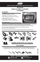
INSTALLATION INSTRUCTIONS FOR PART 99-3010S APPLICATIONS 2010-UP CHEVY CAMARO 99-3010S KIT FEATURES • AXXESS Interface included • DIN Head Unit Provision w/ Pocket • ISO DIN Head Unit Provision w/ Pocket • DDIN Head Unit Provision • ISO Stacked Head Unit Provision • Painted Silver to Match Factory Dash KIT COMPONENTS •A) Radio Trim Panel •B) Radio Housing •C) ISO Brackets •D) ISO Trim Plate •E) DDIN Brackets •F) DDIN Trim Plate •G) Pocket •H) Interface •I) 20 Pin GM Harness •J) 4 Pin Harness w/ Stripped
99-3010S TABLE OF CONTENTS DASH DISASSEMBLY • CHEVY CAMARO 2010-UP . . . . . . . . . . . . . . . . . . 1-3 KIT PREPARATION • CHEVY CAMARO 2010-UP . . . . . . . . . . . . . . . . . . . . 4 KIT ASSEMBLY CHEVY CAMARO 2010-UP • DIN HEAD UNIT PROVISION . . . . . . . . . . . . . . . . . . . 5 • ISO DIN HEAD UNIT PROVISION . . . . . . . . . . . . . . . . 6 • DDIN/STACKED ISO DIN HEAD UNIT PROVISION . . . . . . 7 IINTERFACE WIRING • CHEVY CAMARO 2010-UP . . . . . . . . . . . . . . . . . .
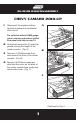
99-3010S DASH DISASSEMBLY CHEVY CAMARO 2010-UP 1 A Disconnect the negative battery terminal to prevent an accidental short circuit. For vehicles without UMQ gauge panel, unsnap and remove shifter trim panel and skip to step 10. 0 30 70 100 12 9 200 19 300 30 180 320 2 Unclip and remove the (2) side trim panels running the length of the center console. (Fig. A) B 3 Remove (1) Phillips screw from each side of the front of the center console. (Fig.
CHEVY CAMARO 2010-UP 5 Remove (2) Phillips screws exposed under the cover on the back of console. (Fig. D) D 0 30 70 100 12 9 200 19 300 30 180 320 6 Remove T20 from front of shifter on Auto Trans., remove shifter. 7 Remove gauge cluster / trim panel around shifter. (Fig. E) 8 Remove shifter surround panel, (4) 7mm bolts, unclip each side and lift up. (Fig.
99-3010S DASH DISASSEMBLY CHEVY CAMARO 2010-UP 9 Lift up on the rear of the console and slide toward the back of the vehicle then unclip and remove the entire center console. (Fig. G) G 10 Remove (2) 9/32” screws securing the climate control/radio trim panel and remove. (Fig. H) 11 Remove (4) Phillips screws securing the radio chassis. (Fig. I) H 12 Reassemble parts together from steps 7-9 and reassemble as one unit after radio installation.
99-3010S KIT PREPARATION CHEVY CAMARO 2010-UP 1 Cut and remove the sub dash radio support to make room for the interface and harnesses. (Fig. A) A 2 Remove panel clips from factory radio and attach to the top of the kit housing. (Fig.
99-3010S KIT ASSEMBLY CHEVY CAMARO 2010-UP DIN HEAD UNIT PROVISION 1 A Refer to the interface wiring and installing section of this manaul. 2 Slide the DIN cage into the Radio Housing and secure by bending the metal locking tabs down. (Fig. A) 3 Snap the Pocket into the bottom opening of the radio housing. (Fig. B) 4 Slide the aftermarket head unit into the cage and secure. (Fig. B) 5 Continue to the INTERFACE WIRING section.
99-3010S KIT ASSEMBLY CHEVY CAMARO 2010-UP ISO DIN HEAD UNIT PROVISION 1 A Refer to the interface wiring and installing section of this manaul. 2 Mount the ISO Brackets to the head unit with the screws supplied with the unit. (Fig. A) 3 Snap the Pocket into the bottom opening of the radio housing. (Fig. B) 4 Slide the head unit into the radio opening until the side clips engage. (Fig. B) B 5 Snap the Trim plate into the Radio Housing. (Fig. C) 6 Continue to the INTERFACE WIRING section.
9-3010S KIT ASSEMBLY CHEVY CAMARO 2010-UP DDIN / STACKED ISO DIN HEAD UNIT PROVISION 1 A Refer to the interface wiring and installing section of this manaul. 2 Cut and remove the center support (For DDIN only). (Fig. A) 3 Snap the Double DIN brackets to the inside edge of the Double DIN radio housing. (Fig.
99-3010S CHEVY CAMARO 2010-UP INTERFACE WIRING *Important: Before beginning any of the following, disconnect the negative battery terminal to prevent an accidental short circuit. The interface is a solution to add an aftermarket radio into GM vehicles. Whether the vehicle is amplified or non-amplified, Onstar, Bluetooth, or steering wheel controls, the interface can retain it. All the warning chimes are retained that are normally lost when the OEM radio is removed.
99-3010S Installing The Interface *Important: Before beginning any of the following, disconnect the negative battery terminal to prevent an accidental short circuit. 1. FROM THE 20 PIN HARNESS: Connect the Red wire to the ignition/accessory wire of the aftermarket radio. Connect the Orange/White wire to the illumination wire of the aftermarket radio. If the aftermarket radio has no illumination wire just tape off the Orange/ White wire.
99-3010S FOR AMPLIFIED SYSTEMS Connect the White rca to the left front low level output of the aftermarket radio. Connect the Gray rca to the right front low level output of the aftermarket radio. Connect the Green rca to the left rear low level output of the aftermarket radio. Connect the Violet rca to the right rear low level output of the aftermarket radio.
99-3010S 3. FROM THE 44 WAY HARNESS: Connect the Black wire to the ground wire of the aftermarket radio. Connect the RCA’s to the AUX in on the aftermarket radio (if equipped) NOTE: This will allow you to retain the 3.5 AUX JACK in the console. Connect the Yellow wire to the 12-volt constant wire of the aftermarket radio. The interface comes set up for amplified systems. If the vehicle is not amplified disconnect the 4 pin harness located between the 44 way and 22 way connector.
99-3010S NOTE: Continue to the TESTING THE INTERFACE section if you do not have factory audio controls on the steering wheel. PROGRAMMING THE STEERING WHEEL CONTROLS 1. 2. 3. 4. 5. Turn on the ignition. The SWC status LED on the interface will begin to blink rapidly. Tap volume up steering wheel control until the LED stops blinking rapidly. The LED will go off when it detects the car. It will then will blink the LED the number corresponding to the radio type. (See Radio Types below).
99-3010S TO FORCE THE UNIT TO RETRY TO AUTO-DETECT THE RADIO: This action must begin 20 seconds AFTER the key is set to ACC ON position OR a steering wheel button is pressed that is NOT Volume Up nor Volume Down. 1) Hold Down VOLUME UP button for 30 seconds. 2) LED will go ON to indicate auto-detecting. (button can be released now) 3) After about 6 seconds, LED will go OFF indicating completion. 4) The LED will then blink the number of times corresponding to the radio ID type it has detected.
99-3010S POTENTIOMETERS from 8 pin harness). Turn clockwise to make gain louder and counterclockwise to make the gain softer. (See figure on pg. 13) ONSTAR LEVEL ADJUSTMENT To adjust the Onstar volume level find the Black/Yellow wire on the 20 pin harness. Push the blue Onstar button, while the voice is speaking tap the Black/Yellow wire to ground.
99-3010S then the 20 seconds you will have to turn the ignition off then back on again. • Within the first 20 seconds if any button other then Volume Up or Volume Down is pushed, the remapping process will stop. • If during the remapping process no button is pushed for 30 seconds the remapping process is aborted and the original settings are reset. SO LET’S BEGIN THE REMAPPING PROCESS: 1) Ideally having the interface visible is recommended since you can see the led flashes to confirm button recognition.
99-3010S 17. Temp Up 18. Temp Down Note: Remember not all radios will have all these commands. Please refer to the radios’ owners manual for specific commands recognized by the radio. For instance the next command to be mapped is the Volume Down command. Let’s say you want the Mode button on your steering wheel to be the Volume Down command. Hold down the Mode button till the led lights up solid red, and then release it. Now your Mode button on the steering wheel is Volume Down.
99-3010S UNLOCKED_DOOR_AUTO_LOCKOUT On or Off AUTO_DOOR_UNLOCK Off, Driver Only, or All Doors DELAYED_LOCK On or Off REMOTE_UNLOCK_LIGHT_FEEDBACK On or Off REMOTE_LOCK_FEEDBACK Off, Lights, Horn, or Lights & Horn REMOTE_DOOR_UNLOCK Driver Only or All Doors Use the optional lcd to adjust these features accordingly: 1. Press the ESC button and PRESS ENTER TO SET LANGUAGE will appear on the screen. 2.
99-3010S 1. Press and hold the Fan Up button to increase Blue. 2. Press and hold the Fan Down button to decrease Blue. 3. After you choose your color stop pressing the buttons and the blinking will stop and the color chosen will stay.
NOTES
NOTES
INSTRUCCIONES PARA LA INSTALACIÓN DE PARTE 99-3010S APLICACIONES 2010-HASTA CHEVY CAMARO 99-3010S CARACTERÍSTICAS DEL KIT • AXXESS Interfaz incluido • Provisión de unidad principal DIN con bolsillo • Provisión de unidad principal ISO DIN con bolsillo • Provisión de unidad principal Doble DIN • Provisión de unidad principal ISO apilada • Pintado en color gris para emparejar el tablero de fabrica COMPONENTES DEL KIT •A) Contorno del panel de radio •B) Caja para la radio •C) Soportes ISO •D) Placa de guar
99-3010S TABLA DE CONTENIDOS DESMONTAJE DEL TABLERO • CHEVY CAMARO 2010-HASTA . . . . . . . . . . . . . . . 1-2 PREPARACION DEL EQUIPO • CHEVY CAMARO 2010-HASTA . . . . . . . . . . . . . . . . . 3 MONTAJE DEL EQUIPO CHEVY CAMARO 2010-HASTA • PROVISION DE UNIDAD PRINCIPAL DIN . . . . . . . . . . . 4 • PROVISION DE UNIDAD PRINCIPAL ISO DIN . . . . . . . . 5 • PROVISION DE UNIDAD PRINCIPAL ISO DIN/DOBLE DIN . 6 CABLEADO DEL INTERFAZ • CHEVY CAMARO 2010-HASTA . . . . . . . . . . . . . . . .
DESMONTAJE DEL TABLERO 99-3010S CHEVY CAMARO 2010-HASTA 1 Desconecte el terminal negativo de la batería para evitar un cortocircuito accidental. A 2 Suelte y retire los (2) paneles de ajuste lateral que corren a lo largo de la consola central. (Figura A) 0 30 70 100 12 9 200 19 300 30 180 320 3 Quite (1) tornillo de 9 / 32 “ de cada lado de la parte frontal de la consola central. (Figura.
DESMONTAJE DEL TABLERO CHEVY CAMARO 2010-HASTA 5 Quite los (2) tornillos de 9 / 32” expuestos bajo la cubierta en la parte posterior de la consola. (Figura D) 6 Levante la parte trasera de la consola y deslice hacia la parte posterior del vehículo luego desenganche y quite todo el centro de la consola (Figura E) 7 Quite los (2) tornillos de 9 / 32” que aseguran los controles climáticos y el tablero de radio. Remuévalo.
PREPARACION DEL EQUIPO 99-3010S CHEVY CAMARO 2010-HASTA 1 A Corte y quite el tablero de apoyo de la radio para hacer espacio para la interfaz y los arneses. (Figura A) 2 Quite los ganchos del panel de la radio de fábrica y adjunte a la parte superior de la caja del equipo.
MONTAJE DEL EQUIPO 99-3010S CHEVY CAMARO 2010-HASTA PROVISION DE UNIDAD PRINCIPAL DIN 1 Consulte el cableado de la interfaz y la sección de instalación de este manual. A 2 Deslice el armazón de DIN en la caja para radio, asegúrela doblando las lengüetas de metal hacia abajo. (Figura A) 3 Encaje el bolsillo en la abertura inferior de la caja de radio. (Figura B) 4 Deslice la unidad principal del mercado de accesorios en la caja y asegúrela. (Figura.
MONTAJE DEL EQUIPO 99-3010S CHEVY CAMARO 2010-HASTA PROVISION DE UNIDAD PRINCIPAL ISO DIN 1 Consulte la sección de instalación y cableado del interfaz de este manual. A 2 Monte los soportes ISO a la unidad principal con los tornillos suministrados con la unidad. (Figura A) 3 Encaje el bolsillo en la abertura inferior de la caja de radio (Figura B) 4 Deslice la unidad principal en la apertura de radio hasta los broches enganchen. (Figura B) B 5 Ajustar la placa de guarnición en la caja para Radio.
MONTAJE DEL EQUIPO 99-3010S CHEVY CAMARO 2010-HASTA PROVISION DE UNIDAD PRINCIPAL DOBLE DIN/ DIN ISO APILADO 1 Consulte la sección de instalación y cableado del interfaz de este manual. A 2 Corte y quite el soporte central (Solamente para DIN Doble). (Figura A) 3 Ajustar los soportes Doble DIN en el borde interior de la caja de radio Doble DIN.
MONTAJE DEL EQUIPO 99-3010S CHEVY CAMARO 2010-HASTA CABLEADO DEL INTERFAZ *Importante: Antes de comenzar cualquiera de los siguientes, desconecte el terminal negativo de la batería para evitar un cortocircuito accidental. La interfaz es la solución cuando se desea agregar una radio del mercado de accesorios en los vehículos GM. Ya sea el vehiculo amplificado, no amplificado, tenga OnStar, Bluetooth o controles en el volante, la interfaz los conservara.
99-3010S Instalación del Interfaz *Importante: Antes de comenzar cualquiera de los siguientes, desconecte el terminal negativo de la batería para evitar un cortocircuito accidental. 1. DESDE EL ARNÉS DE 20 CLAVIJAS: Conecte el cable Rojo con el cable de encendido/accesorios de la radio del mercado secundario. Conecte el cable Naranja / Blanco al cable de iluminación de la radio del mercado de accesorios. Si la radio no tiene cable de iluminación, selle con cinta adhesiva el cable Naranja / Blanco.
99-3010S PARA SISTEMAS AMPLIFICADOS Conecte el cable RCA Blanco en el costado delantero izquierdo de la salida de bajo nivel de la radio del mercado de accesorios. Conecte el cable RCA Gris en el costado delantero derecho de la salida bajo nivel de la radio del mercado de accesorios. Conecte el cable RCA Verde en el costado trasero izquierdo de la salida de bajo nivel de la radio del mercado de accesorios.
99-3010S * Para Radios Eclipse: Conecte el cable de control del Volante (SWC) de Eclipse (Normalmente Marrón y Marrón / Negro) al cable Marrón y al cable Marrón/Blanco del interfaz ASWC. El Cable Marrón conectado al cable Marrón y el cable Marrón/Blanco conectado al cable Marrón/Negro. 3. DESDE EL ARNES DE 44 CLAVIJAS: Conecte el cable Negro al cable de tierra de la radio del mercado de accesorios. Conecte el cable RCA a la entrada AUXILIAR en la radio del mercado de accesorios (si corresponde).
99-3010S INSTALACIÓN DEL INTERFAZ 1. Con todas las conexiones completas, enchufe el arnés de 20 clavijas y el de 22 al interfaz. 2. Vuelva a conectar el terminal negativo de la batería. 3. Conecte el arnés GM de 44 clavijas con arnés del lado del vehículo, y conecte el arnés de radio del mercado de accesorios en la radio del mercado de accesorios.
99-3010S 3) Pulse el botón para SUBIR EL VOLUMEN hasta encontrar el número asociado con su tipo de radio (como se ve en la lista de radios). La luz LED permanecerá encendida mientras mantenga presionado el botón y volverá a parpadear cuando este sea soltado. Por ejemplo: Si la radio es una JVC, pulse el botón para SUBIR EL VOLUMEN 5 veces.
99-3010S Nota: No todas las radios del mercado de accesorios poseen los botones para los comandos del interfaz ASWC en el volante. Las radios de mercado secundario que no cuentan con funciones Bluetooth no reconocerán el PTT (Presione para hablar) o Los comandos “On HOOK / Off HOOK”. Por favor referirse al Manual de la radio o al control remoto para comandos específicos que la radio pueda reconocer. PRUEBA DE LA INTERFAZ Encienda su automóvil y luego encienda la radio de Mercado de accesorios.
99-3010S Para ajustar el volumen general de audio de su vehículo, use un destornillador pequeño para girar el potenciómetro, situado al costado del arnés de 8 clavijas (el más lejano del arnés de 8 clavijas). Gire a la derecha para obtener el volumen más alto y a la izquierda para hacer el volumen más suave AJUSTE DE NIVEL DE ONSTAR Para ajustar el nivel de volumen Onstar busque el cable Negro / Amarillo en el arnés de 20 clavijas.
99-3010S • Si ningún botón es presionado durante los primeros 30 segundos, el proceso de reasignación será abortado y la configuración original será restablecida. COMENCEMOS CON EL PROCESO DE REASIGNACION: 1) Se recomienda tener la interfaz visible, ya que puedes ver todas las luces LED parpadear y así confirmar el reconocimiento de los botones.
99-3010S 16. Bajar Fan 17. Subir Temp 18. Bajar Temp Nota: Recuerde que no todas las radios tendrán todos estos comandos. Por favor refiérase al manual de su radio para los comandos específicos reconocidos por la radio. Por ejemplo, el siguiente comando para ser asignado será el de Bajar el Volumen. Digamos que usted desea que el botón de modo en el volante sea el comando para bajar el volumen. Mantenga presionado el botón de modo hasta que la Luz LED se ilumine en rojo, y luego soltarlo.
99-3010S UBICACION DE LUCES Prendido o Apagado LUCES DE SALIDA Apagado, 30 segundos o 1 minuto PUERTA ABIERTA / CERRADO AUTOMATICO Encendido o Apagado ABRIR PUERTA DEL AUTOMOVIL Apagado, Solo piloto o todas las Puertas CERRAR Prendido o Apagado ABRIR CON CONTROL REMOTO Prendido o Apagado CERRAR CON CONTROL REMOTO Apagado, Luces, Bocina, o Luces y Bocina ABRIR LA PUERTA CON CONTROL REMOTO Solo piloto o todas las puertas Utilice la pantalla LCD opcional para ajustar estas características: 1.
99-3010S 1. ira a “Configurar Color de fondo de pantalla”. La luz de fondo de la pantalla parpadeará mientras que este en este modo. 2. Mantenga pulsado el botón “Face” para aumentar el color Rojo. 3. Mantenga pulsado el botón “Foot” para disminuir el color Rojo. 4. Mantenga pulsado el botón “Foot/Face” para aumentar el color Verde. 5. Mantenga pulsado el botón “Foot/Def” para disminuir el color Verde. 6. Mantenga pulsado el botón “Fan Up” para aumentar el color Azul. 7.
NOTAS
NOTAS