
Vehicle Troubleshooting

VEHICLE TROUBLESHOOTING
AXTC-FD2
REV. 6/11/19© COPYRIGHT 2019 METRA ELECTRONICS CORPORATION
Integrate • AxxessInterfaces.com
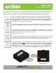
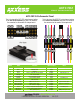
AXTC-FD2 20-Pin Connector Pinout
This is the view of the AXTC-FD2 wiring harness looking
at the front of the connector (pin view). For reference,
the connector has the number 20 stamped onto it.
This is the view of the AXTC-FD2 wiring harness looking
at the back of the connector (wire view). For reference,
the connector has the number 20 stamped onto it.
20 19 18 17 15 14 12 11
10 9 8 7
Wire View
2 1
11 12 14 15 17 18 19 20
Pin View
2 7 8 91 10
1 Yellow 12V+ Battery Power Input Tied with pin-11
2 Pink CAN-HI Data Input
7 Black Ground Input
8 Red 12V+ (5-amp) Accessory Power Output Tied with pin-18
9 Orange 12V+ Illumination Output
10 Blue/White 12V+ Amplifier Turn-On Input
11 Yellow 12V+ Battery Power Input Tied with pin-1
12 Blue/Pink CAN-LO Data Input
14 Red (skinny) SWC 3.5mm Jack + Output Tip of 3.5mm jack
15 White (skinny) SWC 3.5mm Jack - Output Ring of 3.5mm jack
17 Green/Purple 12V+ Reverse Trigger Output
18 Red 12V+ (5-amp) Accessory Power Output Tied with pin-8
19 Light Green 12V- Parking Brake Trigger Output
20 Blue/Pink VSS (speed pulse) Output 4000 pulses per mile
Wire # Color Function Input / Output Notes