
Operation Manual

MI 3309 BT DeltaGT Single test
50
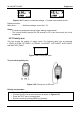
Test with 5IN, 180 (step 4).
(P)RCD should trip-out
Re-activate (P)RCD.
Test with ½IN, 0 (step 5).
(P)RCD should not trip-out
Test with ½IN, 180 (step 6).
(P)RCD should not trip-out
End of test.
Displayed results:
Main results ........... trip-out times at different currents / starting polarities
U ............................ voltage U
L-PE
Notes:
Consider any displayed warning before starting measurement! The symbol
means that the polarity of the mains cord should be changed.
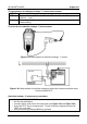
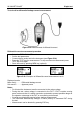
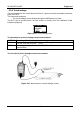
Mains voltage is applied to the (P)RCD under test. Do not touch the equipment
under test or the test cord during the test.
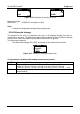
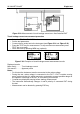
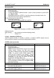
5.2.11 Power test
The DUT’s power consumption is measured in this test. The apparent power is a useful
indication of proper operation of the appliance.
Figure 5.38: Power test menu
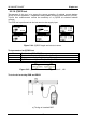
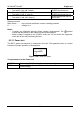
Test parameters for the Power test
OUTPUT Test voltage [MAINS voltage]
TIME Measuring time [2 s, 3 s, 5 s, 10 s, 30 s, 60 s, 120 s, --- s (continuous
measurement)]