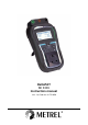
DeltaPAT MI 3309 Instruction manual Ver. 1.0, Code no.
Distributor: Manufacturer: Metrel d.d. Ljubljanska cesta 77 SI-1354 Horjul E-mail: metrel@metrel.si http://www.metrel.si © 2011 Metrel Mark on your equipment certifies that this equipment meets the requirements of the EU (European Union) concerning safety and electromagnetic compatibility regulations No part of this publication may be reproduced or utilized in any form or by any means without permission in writing from METREL.
MI 3309 DeltaPAT Table of contents Table of contents 1 General description.................................................................................................6 1.1 1.2 1.3 1.4 2 Warnings ...............................................................................................................7 Battery and charging .............................................................................................8 New battery cells or cells unused for a longer period ........................
MI 3309 DeltaPAT 5.2.1 5.2.2 5.2.3 5.2.4 5.2.5 5.2.6 5.2.7 5.2.8 5.2.9 5.2.10 5.2.11 5.2.12 5.2.13 6 Table of contents Visual inspection ..........................................................................................31 Earth continuity resistance ...........................................................................32 Insulation resistance.....................................................................................34 Insulation resistance - P .......................................
MI 3309 DeltaPAT Table of contents Appendix A – Barcode formats ......................................................................................69 Appendix B – Simple test codes (UK) ............................................................................70 Appendix C – Autotest shortcut codes (UK) .................................................................
MI 3309 DeltaPAT General description 1 General description The multifunctional portable appliance tester DeltaPAT is intended to perform measurements for testing the electrical safety of portable electrical equipment.
MI 3309 DeltaPAT General description 1.1 Warnings In order to reach a high level of operator safety while carrying out various measurements using the instrument, as well as to keep the test equipment undamaged, it is necessary to consider the following general warnings: Warning on the instrument means »Read the Instruction manual with special care to safety operation«.
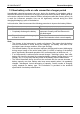
MI 3309 DeltaPAT General description 1.2 Battery and charging The instrument uses six AA size rechargeable NiCd or NiMH battery cells. Alkaline battery cells are not allowed. Battery condition is always displayed in the upper right corner of the display. If the battery power becomes too weak, the instrument indicates this as shown in Figure 1.1. This indication appears for a few seconds and then the instrument turns itself off. Figure 1.
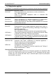
MI 3309 DeltaPAT General description 1.3 New battery cells or cells unused for a longer period Unpredictable chemical processes can occur during the charging of new battery cells or cells that have been left unused for a longer period (more than 3 months). NiMH and NiCd cells can be subjected to these chemical effects (sometimes called the memory effect). As a result the instrument operation time can be significantly reduced during the initial charging/discharging cycles of the batteries.
MI 3309 DeltaPAT General description 1.
MI 3309 DeltaPAT Instrument description 2 Instrument description 2.1 Front panel Figure 2.1: Front panel Legend: 1 2 3 4 5 6 7 8 LCD FAIL PASS TEST UP DOWN MEM TAB 9 ON / OFF ESC 10 128 x 64 dots matrix display with backlight. Red indicator Indicates PASS / FAIL of result. Green indicator Starts testing / confirms selected option. Selects parameter / changes value of selected parameter. Store / recall / clear tests in memory of instrument. Selects the parameters / item / option in selected function.
MI 3309 DeltaPAT Instrument description 2.2 Connector panel Figure 2.2: Connector panel Legend: 1 S/EB 2 IEC 3 LN 4 PE 5 FUSE compartment 6 MAINS 7 USB connector 8 PS/2 connector Probe and Earth continuity terminal IEC test terminal LN terminal (for connection of fixed installed appliances) PE terminal (for connection of fixed installed appliances) Fuses: 2 x T16 A / 250 V; breaking capacity: 1500 A (for protection against overload and short circuit) Mains supply connector and test terminal.
MI 3309 DeltaPAT Instrument description Legend: 1 2 3 4 5 Inserts for side belt Battery compartment cover Fixing screw for battery compartment cover Back side information label Holder for inclined position of the instrument Figure 2.
MI 3309 DeltaPAT Instrument description 2.4 Meaning of symbols and messages on the instrument display Before performing a measurement, the instrument performs a series of pre-tests to ensure safety and to prevent any damage. These safety pre-tests are checking for any external voltage and load condition on test terminals. If a pre-test fails, an appropriate warning message will be displayed. Warnings and protective measures are described in this chapter. WARNING! Improper supply voltage warning.
MI 3309 DeltaPAT Instrument description WARNING! A high resistance between L and N was measured in the fuse pre-test. This indication means that the device under test has very low power consumption or it is: not connected; switched off; contains a fuse that has blown. Select PROCEED or CANCEL.
MI 3309 DeltaPAT Instrument description WARNING! A high voltage will be present on the output of the instrument! WARNING! A high insulation test voltage is present on the output of the instrument. Measurement is in progress. Test result can be saved. Connect the test lead to the S/EB test terminal. Flex the mains cable of appliance during the test. Check that the device under test is switched on (to ensure that the complete circuit is tested). Connect the cord to be tested to the IEC test terminal.
MI 3309 DeltaPAT Instrument description 2.4.1 Battery indication The indication shows the charge condition of battery and connection of external charger. Battery capacity indication. Low battery. Battery is too weak to guarantee correct result. Replace or recharge the battery cells.
MI 3309 DeltaPAT Technical specifications 3 Technical specifications 3.1 Earth continuity Range 0.00 19.99 20.0 199.9 200 1999 Resolution 0.01 0.1 1 Accuracy (5 % of reading + 3 digits) Indication only Powered by............................... battery or mains Test currents............................. 200 mA into 2.00 Open circuit voltage .................. <9 V AC Pass levels................................ 0.10 , 0.20 , 0.30 , 0.40 , 0.50 , 0.60 , 0.70 , 0.80 , 0.
MI 3309 DeltaPAT Technical specifications 3.3 Substitute leakage current, Substitute leakage – P current Range 0.00 mA 9.99 mA 10.0 mA 20.0 mA Resolution 0.01 mA 0.1 mA Accuracy (5 % of reading + 3 digits) Powered by............................... battery or mains Open circuit voltage .................. <50 V AC at rated mains voltage Short circuit current................... <40 mA Pass levels: Substitute leakage .................... 0.25 mA, 0.50 mA, 0.75 mA, 1.00 mA, 1.50 mA, 2.
MI 3309 DeltaPAT Technical specifications 3.5 Differential leakage current Range 0.00 mA 19.99 mA Resolution 0.01 mA Accuracy (5 % of reading + 5 digits) Apparent power ................ Indication only Influence of load current……….≤ 0.01mA / A Powered by....................... mains Pass levels:....................... 0.25 mA, 0.50 mA, 0.75 mA, 1.00 mA, 1.50 mA, 2.00 mA, 2.25 mA, 2.50 mA, 3.50 mA, 4.00 mA, 4.50 mA, 5.00 mA, 5.50 mA, 6.00 mA, 7.00 mA, 8.00 mA, 9.00 mA, 10.00 mA, 15.
MI 3309 DeltaPAT Technical specifications Test current..................... ½I N , I N , 5I N (I N = 10 mA, 15 mA, 30 mA) Start angle ...................... 0, 180, both Test modes ..................... single, autotest Test terminals MAINS terminal Specified accuracy is valid for complete operating range. 3.7.2 Portable RCD trip-out time Range 0 ms 300 ms(½I N ) 0 ms 300 ms (I N ) 0 ms 40 ms (5I N ) Resolution 0.1 ms 0.1 ms 0.1 ms Accuracy 3 ms 1 ms Powered by..................
MI 3309 DeltaPAT Technical specifications 3.10 General data Power supply voltage........................ 9 V DC (61.2 V NiMH or NiCd battery, type HR 6) (size AA) Operation .......................................... typical 8 h Battery charging current.................... 250 mA (internally regulated) Overvoltage category......................... CAT II / 300 V Protection classification .................... double insulation Pollution degree................................ 2 Protection degree case ......
MI 3309 DeltaPAT Main menu and test modes 4 Main menu and test modes 4.1 Instrument Main menu From the Main menu of the instrument there are five instrument operation modes, Help menu and Setup menu can be selected: Figure 4.1: Instrument Main menu Keys: / TAB TEST Select one of the following menu items: simple pre-programmed sequences, can be redefined by the user, see chapter 6.1 Simple test.
MI 3309 DeltaPAT Main menu and test modes 4.3 Shortcut menu In this menu are all the most popular pre-defined autotest sequences that can be selected and performed (shown in Appendix C). When an autotest sequence has been completed, the measurement results can be stored into instrument internal memory. Figure 4.3: Autotest shortcut menu example See chapter 6.3 Carrying out (Simple, Shortcut) test sequences. 4.4 Single test menu In single test menu individual tests can be performed. Figure 4.
MI 3309 DeltaPAT Main menu and test modes Figure 4.
MI 3309 DeltaPAT Main menu and test modes 4.6.3 LCD contrast and backlight In this menu the contrast and backlight mode of the LCD can be set. Figure 4.9: LCD contrast menu Backlight modes: AUTO OFF ON The high backlight level is active for 30 seconds after last pressing of any key. Then the backlight level returns to low level until a key is pressed again. Backlight level is low. Backlight level is high.
MI 3309 DeltaPAT Main menu and test modes The substitute leakage results will be lower if the nominal voltage is set to 110 V! Take care that the nominal voltage is set correctly! 4.6.5 Shortcut setup In this menu the available list of available shortcut codes can be set. Basic Shortcuts only makes the most important shortcuts available in the Shortcut menu while the Advanced Shortcuts makes all shortcuts available from the Shortcut Menu. Figure 4.
MI 3309 DeltaPAT Main menu and test modes 4.6.7 Setting date and time Date and time can be set in this menu. Figure 4.13: Date and time menu Keys: TAB / TEST ESC Selects the field to be changed. Modifies selected field. Confirms selection and returns to Setup menu. Returns to Setup menu without changes. Note: Date is attached to each stored autotest result. Warning: If the batteries are removed for more than 1 minute the set time and date will be lost. 4.6.
MI 3309 DeltaPAT / TEST MEM ESC Main menu and test modes Selects a letter. Selects the next letter. Confirms name and returns to User data menu. Deletes last letter. Returns to User data menu without changes. Notes: The selected user will be printed on the simple label (initials). Five different user names can be set. 4.6.
MI 3309 DeltaPAT TEST ESC 4.6.11 Main menu and test modes Confirms selection and returns to Main menu. Returns to Setup menu without changes. Communication port In this menu the communication parameters can be set. setting the USB or RS232 port for communication with PC. setting the baud rate. Figure 4.18: Communication menu Keys: TAB / TEST ESC Switches between options. Selects the active communication port / Selects baud rate. Confirms selection and returns to Setup menu.
MI 3309 DeltaPAT Single test 5 Single test In a Single test mode individual tests can be performed. This is especially helpful for troubleshooting. 5.1 Performing measurements in single test mode Select appropriate test in Single test menu. Figure 5.1: Single test menu Keys: / TEST ESC Selects a single test. Enters Single test measuring menu. Returns to Main menu. A single test can be started from any Single test measuring menu. Before carrying out a test the parameters / limits can be edited.
MI 3309 DeltaPAT Single test Any signs of pollution, moisture, dirt that can jeopardize safety. Especially openings, air filters, protection covers and barriers must be checked! Are there signs of corrosion? Are there signs of overheating? Inscriptions and markings related to safety must be clearly readable. Installation of the device under test must be performed according to the instruction manual. During visual inspection the measuring points for the electrical testing have to be determined too.
MI 3309 DeltaPAT Single test Typical test circuits for Earth continuity resistance measurement Figure 5.5: Measurement of Earth continuity Figure 5.6: Measurement of Earth continuity of fixed installed DUTs of Class I Earth continuity resistance measurement procedure Select the EARTH CONT. function. Set the test parameters. Connect device under test to the instrument (see figure 5.5 and figure 5.6). Press the TEST key for measurement. To stop continuous measurement press TEST key once again.
MI 3309 DeltaPAT Single test Figure 5.7: Examples of Earth continuity resistance measurement results Displayed results: Main result ............. Earth continuity resistance Note: Consider displayed warnings before starting measurement! It is recommended that the mains cable is folded during the test. 5.2.3 Insulation resistance The insulation resistance test checks the resistance between live conductors and earthed (or isolated) accessible metal parts of a device under test.
MI 3309 DeltaPAT Single test Figure 5.9: Measurement of insulation resistance Figure 5.10: Measurement of insulation resistance of fixed installed DUTs of Class I Insulation resistance measurement procedure Select the INSULATION function. Set the test parameters. Connect device under test to the instrument (see figure 5.9 and figure 5.10). Press the TEST key for measurement. To stop continuous measurement press TEST key once again. Store the result by pressing MEM key (optional). Figure 5.
MI 3309 DeltaPAT Single test Notes: When S/EB probe is connected during the test then the current through it is also considered. Consider any warning on the display before starting the measurement! Do not touch or disconnect the device under test during the measurement or before it is fully discharged! The message »Udisch …« will be displayed while the voltage on the device is higher than 10 V! 5.2.
MI 3309 DeltaPAT Single test Figure 5.14: Measurement of insulation resistance of fixed installed DUTs Insulation resistance - P measurement procedure Select the INSULATION-P function. Set the test parameters. Connect device under test to the instrument (see figure 5.13 and figure 5.14). Press the TEST key for measurement. To stop continuous measurement press TEST key once again. Store the result by pressing MEM key (optional). Figure 5.
MI 3309 DeltaPAT Single test Figure 5.16: Substitute leakage menu Test parameters for Substitute leakage current measurement OUTPUT LIMIT TIME Test voltage [30 V] Maximum current [0.25 mA, 0.50 mA, 0.75 mA, 1.00 mA, 1.50 mA, 2.00 mA, 2.25 mA, 2.50 mA, 3.50 mA, 4.00 mA, 4.50 mA, 5.00 mA, 5.50 mA, 6.00 mA, 7.00 mA, 8.00 mA, 9.00 mA, 10.0 mA, 15.
MI 3309 DeltaPAT Single test Substitute leakage measurement procedure Select the SUB. LEAKAGE function. Set the test parameters. Connect device under test to the instrument (see figures 5.17 and figures 5.18). Press the TEST key for measurement. To stop continuous measurement press TEST key once again. Store the result by pressing MEM key (optional). Figure 5.19: Example of substitute leakage current measurement results Displayed results: Main result .............
MI 3309 DeltaPAT TIME Single test 2.00 mA, --- mA] Measuring time [2 s, 3 s, 5 s, 10 s, 30 s, 60 s, 120 s, --- s (continuous measurement)] Test circuits for substitute leakage - P measurement Figure 5.21: Measurement of Substitute leakage - P current Figure 5.22: Measurement of substitute leakage of accessible isolated conductive parts of fixed installed DUTs Substitute leakage - P measurement procedure Select the SUB. LEAKAGE-P function. Set the test parameters.
MI 3309 DeltaPAT Single test Figure 5.23: Example of substitute leakage - P current measurement results Displayed results: Main result…………..Substitute leakage current (LN – P) Notes: Consider any displayed warning before starting measurement! The currents flowing through the PE terminal or PE of the test socket will not be considered. 5.2.7 Polarity test This test checks the polarity of supply cords.
MI 3309 DeltaPAT Single test Figure 5.26: Examples of polarity test result Displayed results: Main result ............. PASS/FAIL, description of fault Note: Consider any displayed warnings before starting test! 5.2.8 Differential leakage The purpose of this test is to determine the sum of all leakages flowing from the live conductors to the earth. The differential method allows measuring the full and true leakage current, even if there are parallel current paths from the DUT to ground.
MI 3309 DeltaPAT Single test Differential current measurement procedure Select the DIFF. LEAKAGE function. Set the test parameters. Connect device under test to the instrument (see figure 5.28). Press the TEST key for measurement. To stop continuous measurement press TEST key once again. Store the result by pressing MEM key (optional). Figure 5.29: Examples of differential current measurement result Displayed results: Main result I ........... Differential leakage current Sub-result P.........
MI 3309 DeltaPAT Single test Test circuits for touch leakage current measurement Figure 5.31: Measurement of touch leakage current Figure 5.32: Measurement of touch leakage current on a fixed installed DUT Touch leakage current measurement procedure Select the TOUCH LEAKAGE function. Set the test parameters. Connect device under test to the instrument (see figure 5.31 and figure 5.32). Press the TEST key for measurement. To stop continuous measurement press TEST key once again.
MI 3309 DeltaPAT Single test Figure 5.33: Examples of touch leakage current measurement results Displayed results: Main result I ........... Touch leakage current Sub-result P............Apparent power Notes: For this test the instrument must be connected to the mains voltage. During the test, mains voltage is connected to the DUT.
MI 3309 DeltaPAT Single test a) Testing of standard RCD b) Testing of PRCD via mains socket c) Testing of PRCD via test socket Figure 5.36: Testing of RCD and PRCD 5.2.10.1 (P)RCD single test In single test a fast (P)RCD test with selected test current and with one or both starting polarities is performed. Trip-out time measurement procedure Measuring PRCD Select the RCD test function. Select test mode. Set test parameters. Connect tested PRCD / device to an external voltage socket.
MI 3309 DeltaPAT Single test If both starting polarities are selected: Reactivate tested PRCD. Store the result by pressing MEM key (optional). or Select the PRCD test function. Select test mode. Set test parameters. Connect tested PRCD between test socket and IEC connector of the DeltaPAT (see figure 5.36c), and connect instrument’s MAINS terminal to an external voltage socket. Depending on the type of PRCD, it may be necessary to manually switch it on.
MI 3309 DeltaPAT Single test voltage socket. Connect the IEC cord to the instrument´s MAINS terminal and PRCD (see figure 5.36b). Or connect tested PRCD between test socket and IEC connector of the DeltaPAT Connect the instrument to mains voltage (see figure 5.36c). Depending on the type of PRCD, it may be necessary to manually switch it on. RCD: Connect the DeltaPAT MAINS terminal to mains socket protected by tested RCD (see figure 5.36a).
MI 3309 DeltaPAT Single test Test circuit for the power test Figure 5.39: Power test Functional test procedure Select the POWER function. Set test parameters. Connect device under test to the instrument’s test socket and switch it on (see figure 5.39). Connect the instrument to mains voltage. Press the TEST key for measurement. To stop continuous measurement press TEST key once again. Store the result by pressing MEM key (optional). Figure 5.
MI 3309 DeltaPAT 5.2.12 Single test Voltage TRMS In this function the voltage across the MAINS terminal is measured continuously. Test circuit for voltage measurement Figure 5.42: Voltage measurement with the IEC cord Voltage TRMS procedure Select the VOLTAGE TRMS function. Connect the IEC cord to the instrument’s MAINS terminal and to the external mains socket as shown on figure 5.42. Store the result by pressing MEM key (optional). Figure 5.
MI 3309 DeltaPAT Single test Scope of test Check following items while the appliance is operating: RCDs and other disconnection devices. How hot the appliance becomes during operation. Rotating parts, fans, etc. Power consumption. Lamps and indicators. Etc. Especially safety relevant functions should be checked. Functional test procedure Select the FUNCTIONAL TEST function. Plug the device under test to the instrument’s test socket and supply the instrument.
MI 3309 DeltaPAT Automatic test sequences 6 Automatic test sequences Simple test and Shortcut autotest are the fastest (autotest) modes for testing appliances. In both test modes pre-programmed measurements run automatically in a sequential order. The complete autotest results can be stored together with the associated appliance ID and appliance NAME. 6.1 Simple test Up to 50 customized sequences can be pre-programmed in this test mode. Typical simple test sequences are added to the list by default.
MI 3309 DeltaPAT Automatic test sequences -a Normal polarity test If Active polarity test is set. The operator must decide by itself if the alternative tests are applicable. Refer to chapter 1.1 Warnings for more information. 6.3 Selecting the autotest shortcut sequence Select SHORTCUT MENU in Main menu. The autotest sequence can be selected with three-digit test code or on base of selected appliances type, class and other parameters. Figure 6.
MI 3309 DeltaPAT Automatic test sequences Notes If any of the inspections are marked as failed or if any test fails the test sequence is stopped and the instrument automatically goes to the Result menu. If a test parameter (limit, duration, output voltage) is changed the setup is valid only for the particular test. If the test limit, output voltage or test duration is changed in Shortcut autotest sequence the autotest code will not be stored (as the settings do not correspond with the code anymore).
MI 3309 DeltaPAT Automatic test sequences Figure 6.7: Insulation resistance starting screen After the measurement is carried out the Insulation result screen is displayed. Figure 6.8: Insulation result screen There are no special options to be set in the Insulation resistance result screen. 6.4.4 Substitute leakage measurement The test is offered if it is applicable according to the autotest setting. The Substitute leakage current starting screen is displayed first.
MI 3309 DeltaPAT Automatic test sequences 6.4.5 Differential leakage measurement The test is offered if it is applicable according to the autotest setting. The Differential leakage current starting screen is displayed first. Measurement and options in Differential leakage starting screen are described in chapter 5.2.8 Differential leakage. Figure 6.11: Differential leakage starting screen After the measurement is carried out the Differential leakage result screen is displayed. Figure 6.
MI 3309 DeltaPAT Automatic test sequences 6.4.7 Substitute Leakage - P measurement The test is offered if it is applicable according to the autotest setting. The Substitute leakage - P starting screen is displayed first. Measurement and options in Substitute leakage - P starting screen are described in chapter 5.2.6 Substitute leakage - P. Figure 6.15: Substitute leakage - P starting screen After the measurement is carried out the Substitute leakage - P result screen is displayed. Figure 6.
MI 3309 DeltaPAT Automatic test sequences 6.4.9 (P)RCD test The test is offered if it is applicable according to the autotest setting. The (P)RCD test starting screen is displayed first. Measurement and options in (P)RCD test starting screen are described in chapter 5.2.10 RCD test. (P)RCD single test menus (P)RCD autotest menu Figure 6.19: (P)RCD test starting screen After the measurement is carried out the (P)RCD test result screen is displayed. Figure 6.
MI 3309 DeltaPAT 6.4.11 Automatic test sequences Power test The test is offered if it is applicable according to the autotest setting. The Power starting screen is displayed first. Measurement and options in Power starting screen are described in chapter 5.2.11 Power test. Figure 6.23: Power starting screen After the measurement is carried out the Power result screen is displayed. Figure 6.24: Power result screen There are no special options to be set in the Power result screen. 6.4.
MI 3309 DeltaPAT Automatic test sequences 6.5 Handling autotest results After the Simple / Shortcut autotest is finished, the Main autotest result screen will be displayed including an overall / indication. Figure 6.26: Main autotest result screen Options in Autotest results screen: Views individual results. VIEW RESULTS Returns to Simple or Shortcut menu. NEW TEST Saves Autotest results. Refer to chapter 7.
MI 3309 DeltaPAT Working with autotest results 7 Working with autotest results 7.1 Saving autotest results After selecting Save results in Autotest results menu, the autotest results will be stored in the internal memory of the instrument. The appliance ID number and NAME can be added to the test results before the results are saved: Figure 7.1: Save results menu (Appliance ID) Keys: / , TEST MEM (OK) ESC (DEL) ESC (CANCEL) Edit Appliance ID data. Saves Appliance ID.
MI 3309 DeltaPAT Working with autotest results 7.2 Recalling results Saved autotest results can be recalled, printed or deleted from the Memory menu. Enter the Memory menu from the Setup menu. Figure 7.4: Memory menu To enter the Recall results menu select Recall results in Memory menu. A list of Appliance ID’s and NAMES are displayed in a chronological order (last performed measurement is displayed at the bottom of the list).
MI 3309 DeltaPAT Working with autotest results 7.3 Deleting individual autotest results To enter the Delete results menu select Delete results in Memory menu. A list of Appliance ID’s and NAMES are displayed in a chronological order (last performed measurement will be displayed at the bottom of the list). In the lower window of the display the following data is displayed: Appliance ID, NAME; date and time of the selected test; the overall / status of the selected test. Figure 7.
MI 3309 DeltaPAT Working with autotest results 7.5 Printing and RFID tagging of individual autotest results To print labels or results and write RFID tags select Print data / RFID in Memory menu. A list of Appliance ID’s and NAMES are displayed in a chronological order (last performed measurement will be displayed at the bottom of the list).
MI 3309 DeltaPAT Communication 8 Communication The instrument can communicate with the PATLink PRO PC software. The following actions are supported: Saved results can be downloaded and stored to a PC. Custom Simple test sequences can be uploaded to the instrument. There are two communication interfaces available on the instrument: USB or RS232. See chapter 4.6.11 Communication port for more information.
MI 3309 DeltaPAT Measuring 110 V appliences 9 Measuring 110 V appliences The DeltaPAT instrument allows measurements to be performed on 110 V appliances. When the 110 V adapter is used only the following measurements can be performed: Earth continuity resistance, Insulation resistance, Insulation resistance - P, Substitute leakage current, Substitute leakage current - P. Other measurements are prohibited in order to prevent damage of the tested appliance. 9.
MI 3309 DeltaPAT Maintenance 10 Maintenance 10.1 Periodic calibration It is essential that all measuring instruments are regularly calibrated in order for the technical specification listed in this manual to be guaranteed. We recommend an annual calibration. The calibration has to be done by an authorized technical person only. 10.
MI 3309 DeltaPAT Instrument set and accessories 11 Instrument set and accessories Standard set of the instrument Instrument MI 3309 DeltaPAT Test probe, black Crocodile clip, black Test lead, 1.5 m, black 2 x IEC cord, 1.
MI 3309 DeltaPAT Appendix A – Barcode formats Appendix A – Barcode formats The instrument DeltaPAT supports two barcode formats (single and double). Autotest code and appliance ID Autotest codes are represented as a three digits code. These autotest codes can also be represented by the barcode. Using the barcode scanner, the instruments can accept autotest code from barcode label. A0 1 Autotest code Also appliance ID can be read from barcode label.
MI 3311 DeltaPAT Appendix B – Simple test codes (UK) Appendix B – Simple test codes (UK) Type Class Earth continuity Limit Out Insulation Limit Out S. Leakage Limit Polarity CLASS I CLASS II IEC CLASS I PC I II I 0.20 Ω 0.20 Ω 0.20 Ω 1.00 MΩ 2.00 MΩ 1.00 MΩ 1.00 MΩ 0.75 mA 0.25 mA 0.
MI 3311 DeltaPAT Appendix C – Autotest shortcut codes (UK) Appendix C – Autotest shortcut codes (UK) Autotests marked bold are available if SHORTCUT setup is set to BASIC. Refer to chapter 4.6.5 Shortcut Setup for more information. Type Class Fuse Cord Earth Bond Limit Out Insulation Limit Out S. Leakage Leakage Limit Limit T. Leakage Code Limit I I I I 3A 6A 10 A 13 A short short short short 0.10 Ω 0.10 Ω 0.10 Ω 0.10 Ω 10 A 10 A 25 A 25 A 1.00 MΩ 1.00 MΩ 1.00 MΩ 1.
MI 3309 DeltaGT Type Appendix C – Pre-programmed autotests (UK) Class Fuse Cord Earth Bond Limit Out Insulation Limit Out S. Leakage Leakage Limit Limit T. Leakage Code Limit I I I I 3A 6A 10 A 13 A short short short short 0.10Ω 0.10 Ω 0.10 Ω 0.10 Ω 10 A 10 A 25 A 25 A - - - 0.75 mA 1.00 mA 1.50 mA 2.25 mA - 027 028 029 030 I I I I 3A 6A 10 A 13 A short short short short 0.10 Ω 0.10 Ω 0.10 Ω 0.10 Ω 10 A 10 A 25 A 25 A - - 0.75 mA 1.00 mA 1.50 mA 2.
MI 3309 DeltaGT Appendix C – Pre-programmed autotests (UK) I 13 A long 0.50 Ω 25 A 1.00 MΩ 500 V - - - 064 II II - - - 2.00 MΩ 500 V 2.00 MΩ 500 V - 0.25 mA - - 065 066 - IEC leads Surge protected = OFF / RCD protected = OFF Length 0.5mm2 / 3A 0.75mm2 / 6 A 1 mm2/ 10 A 1.25mm2/ 13A 1.5mm2/ 15 A Earth Bond Limit Out Insulation Limit Out Polarity Code <=5 m 7.5 m 10 m 12 m 15 m 20 m 30 m 40 m 50 m 0.30 Ω 0.40 Ω 0.50 Ω 0.60 Ω 0.70 Ω 0.80 Ω 1.00 Ω 2.00 Ω 2.
MI 3309 DeltaGT Appendix C – Pre-programmed autotests (UK) IEC leads Surge protected = ON RCD protected = OFF Length 0.5mm2 / 3A 0.75mm2 / 6 A 1 mm2/ 10 A 1.25mm2/ 13A 1.5mm2/ 15 A Earth Bond Limit Out Insulation Limit Out Polarity Code <=5 m 7.5 m 10 m 12 m 15 m 20 m 30 m 40 m 50 m 0.30 Ω 0.40 Ω 0.50 Ω 0.60 Ω 0.70 Ω 0.80 Ω 1.00 Ω 2.00 Ω 2.00 Ω 10 A 10 A 10 A 10 A 10 A 10 A 10 A 10 A 10 A 1.00 MΩ 1.00 MΩ 1.00 MΩ 1.00 MΩ 1.00 MΩ 1.00 MΩ 1.00 MΩ 1.00 MΩ 1.
MI 3309 DeltaGT Appendix C – Pre-programmed autotests (UK) IEC leads Surge protected = OFF RCD protected = ON Length 0.5mm2 / 3A Earth Bond Limit Out Leakage Limit <=5 m 0.30 Ω 10 A 0.75 mA 7.5 m 0.40 Ω 10 A 0.75 mA 10 m 0.50 Ω 10 A 0.75 mA 12 m 0.60 Ω 10 A 0.75 mA 15 m 0.70 Ω 10 A 0.75 mA 20 m 0.80 Ω 10 A 0.75 mA 30 m 1.00 Ω 10 A 0.75 mA 40 m 2.00 Ω 10 A 0.75 mA 50 m 2.00 Ω 10 A 0.75 mA <=5 m 0.20 Ω 10 A 0.75 mA 7.5 m 0.30 Ω 10 A 0.75 mA 10 m 0.
MI 3309 DeltaGT Appendix C – Pre-programmed autotests (UK) 12 m 0.30 Ω 25 A 0.75 mA PRCD: 30 mA Auto active 297 <=5 m 0.20 Ω 25 A 0.75 mA active 303 7.5 m 0.20 Ω 25 A 0.75 mA active 304 10 m 0.20 Ω 25 A 0.75 mA active 305 12 m 0.30 Ω 25 A 0.75 mA active 306 15 m 0.30 Ω 25 A 0.75 mA PRCD: 30 mA Auto PRCD: 30 mA Auto PRCD: 30 mA Auto PRCD: 30 mA Auto PRCD: 30 mA Auto active 307 <=5 m 0.20 Ω 25 A 0.75 mA active 312 7.5 m 0.20 Ω 25 A 0.