
Operation Manual


MI 3309 DeltaPAT Single test
34
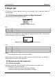
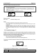
Figure 5.7: Examples of Earth continuity resistance measurement results
Displayed results:
Main result ............. Earth continuity resistance
Note:
Consider displayed warnings before starting measurement!
It is recommended that the mains cable is folded during the test.
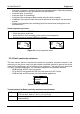
5.2.3 Insulation resistance
The insulation resistance test checks the resistance between live conductors and earthed
(or isolated) accessible metal parts of a device under test. This test can disclose faults
caused by pollution, moisture, deterioration of the insulation material etc.
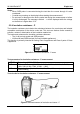
The instrument measures the insulation resistance between:
The (L+N) on test socket and PE terminal on test socket / (S/EB) terminal;
LN terminal and PE terminal / (S/EB) terminal (for fixed installed appliances).
This function is primarily intended for testing Class I appliances.
Figure 5.8: Insulation menu
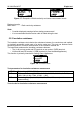
Test parameters for insulation resistance measurement
Test voltage [250 V, 500 V] OUTPUT
LIMIT
Minimum resistance [0.01 M, 0.10 M, 0.25 M, 0.30 M, 0.50 M,
1 M, 2 M, 4 M, 7 M, 10 M, --- M]
TIME Measuring time [2 s, 3 s, 5 s, 10 s, 30 s, 60 s, 120 s, --- s (continuous
measurement)]
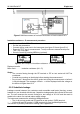
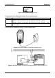
Test circuits for Insulation resistance measurement