
Operation Manual


MI 3309 DeltaPAT Single test
39
Substitute leakage measurement procedure
Select the SUB. LEAKAGE function.
Set the test parameters.
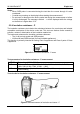
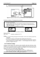
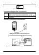
Connect device under test to the instrument (see figures 5.17 and figures 5.18).
Press the TEST key for measurement. To stop continuous measurement press
TEST key once again.
Store the result by pressing MEM key (optional).
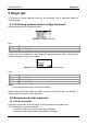
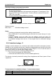
Figure 5.19: Example of substitute leakage current measurement results
Displayed results:
Main result ............. Substitute leakage current
Notes:
Consider any displayed warning before starting measurement!
When S/EB probe is connected during the test then the current through it is also
considered.
Substitute leakage result may differ from the leakage current test result. For
example, if EM filter capacitors are connected to the phase and neutral conductors,
the substitute leakage result can be 2 times higher than the differential leakage
result.
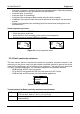
5.2.6 Substitute leakage - P
Leakage currents between live conductors and isolated accessible metal parts (screws,
handles etc.) are checked with this test. Capacitive leakage paths are included in the result
too. The test measures the current flowing at a test voltage of 30 V AC and the result is
scaled to the value of a nominal mains supply voltage.
The instrument measures the substitute leakage between:
The (L+N) on test socket and S/EB terminal;
LN terminal and S/EB terminal (for fixed installed appliances).
This function is primarily intended for testing Class II appliances and Class II parts of Class
I appliances.
Figure 5.20: Substitute leakage - P menu
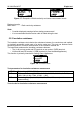
Test parameters for substitute leakage - P current measurement
OUTPUT Test voltage [30 V]
LIMIT Maximum current [0.25 mA, 0.50 mA, 0.75 mA, 1.00 mA, 1.50 mA,